Resources
|
English • العربية • български • català • čeština • Deutsch • Ελληνικά • español • فارسی • français • hrvatski • magyar • italiano • română • 日本語 • 한국어 • lietuvių • Nederlands • norsk • polski • português • русский • Türkçe • українська • 中文(中国大陆) • 中文(台灣) • עברית • azərbaycanca • |
About | Development | Community | RepRap Machines | Resources | Policy
This page has been flagged as containing duplicate material. An editor has suggested merging this page or section into RepRap Options . (Discuss)
This page is a work in progress and contains outdate information, treat this like a placeholder
Contents
Software Toolchain
The software toolchain can be roughly broken down into 3 parts:
- CAD tools.
- CAM tools.
- Firmware for electronics.
CAD Tools
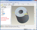
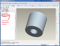
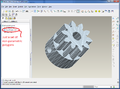
Computer Aided Design, or CAD, tools are used to design 3D parts for printing.
Software
CAD tools in the truest sense are designed to allow you to easily change and manipulate parts based on parameters. Sometimes CAD files are referred to as parametric files. They usually represent parts or assemblies in terms of Constructive Solid Geometry, or CSG. Using CSG, parts can be represented as a tree of boolean operations performed on primitive shapes such as cubes, spheres, cylinders, pyramids, ETC.
Free/Libre/Open Source Software (FLOSS) applications that fall into this category would be OpenSCAD, FreeCAD and HeeksCAD and more. Examples of proprietary and fully parametric CAD tools are PTC Creo (formerly PTC Pro/Engineer), Dassault Solidworks, Autodesk Inventor and more.
Typically in such programs the geometry is stored in a feature tree where the dimensions can be modified numerically, and the geometry is then regenerated with great precision. The geometry is a mathematical representation where, for example, a circle is generated from its center, radius and plane parameters (hence, "parametric"). No matter how much you zoom in, a circle is still curved, and the CAD program has no problem finding its center when you click on it. This can be quite beneficial when making drawings with dimensions between the circle and sections that need to be concentrically removed.
Another looser category of CAD tool would be apps that represent parts as a 3D Polygon mesh. These applications are meant to be used more for special effects and artistic applications. They also seem to be a little more user-friendly. FLOSS-apps in this category would be Blender and Art of Illusion. Proprietary tools are Autodesk 3ds Max, Autodesk Alias, Google Sketchup and more.
Further, you can create forms with just a web-browser at certain websites, such as TinkerCAD.com (easy) or 3DTin.com (more sophisticated), those permit you to download the resulting geometry.
Some of the tools mentioned above also use parametric data to generate the geometries, but a lot just register the positions of the vertices of the polygons making up the models. Some use parameters to generate the geometry but then drops that data once the vertices are placed. A curve is thus actually an approximation, generated from a number of straight lines between points. As such, those tools are better suited for design where the precision of dimensions are less important than looks and ease of use.
If you want to print as little material as possible; design parts optimised by volume in function of strains, you may use topology optimization through non-commercial-use-only software such as Topostruct (see sawapan.eu website), BESO, or free-open-source-use such as Topy, a topology optimization software writen in Python by the brillant William Hunter. (ToPy at Google Code; a few related tools at topology-optimisation at github).
It might be usefull to have a lattice engineering software, that will create a support of your part or fill the part to save material. One of the most used is Materialise Magics, but there is also Netfabb. Both are proprietary softwares, not free.
Files
Most of the time 3D software apps save their files in an application-specific format, which in the case of proprietary CAD tools usually are frequently changed and heavily guarded trade secrets.
There are very few interchangeable CAD file formats. The two most widely used interchangeable CSG file formats are STEP and IGES. Both strip the geometries from parametric data and offer only "dead" solids. Features can be added and removed, but the base shape is locked. There is to date no industry-wide interchangeable file format that retain parametric data.
The most widely used interchangeable mesh file format is STL. STL files are important because, as we will see below, they are used by CAM tools.
Mesh files cannot be converted into CSG file formats because they contain no parametric data - only the coordinates of the polygon vertices that make up the solid volume. However, CSG file formats can be converted into mesh file formats.
Thus, if you're designing a part, it's a good idea to design it using a CSG CAD application and save and distribute its original parametric file along with generated STL files.
Parametric file format
STEP export format
STL mesh format


CAM Tools
Computer Aided Manufacturing, or CAM, tools handle the intermediate step of translating CAD files into a machine-friendly format used by the RepRap's electronics. More info is on the CAM Toolchains page.
Software
Slicing Software
In order to turn a 3D part into a machine friendly format, CAM software needs an STL file. The machine friendly format that is used for printing is called G-code. Early versions of RepRaps used a protocol called SNAP but industry standard G-codes are now used. To Convert STL files to G-code, you can use one of the following programs:
- MatterSlice (Fast and full featured - works with MatterControl)(open source)
- Skeinforge (Dated solution)(Still one of the best and highly recommended for accurate prints)
- Cura (Also includes G-Code sender)(Extremely fast and accurate)
- Slic3r (Popular solution for most RepRappers)(Lots of bugs in every release)
- Kisslicer (Fast and accurate with very few bugs)(Closed source)
- RepSnapper
- RepRap Host Software
- X2sw
- SuperSkein
- SlicerCloud (Online Slic3r solution)
- Simplify3D (All-In-One Paid Suite)
The STL to G-code conversion slices the part like salami, then looks at the cross section of each slice and figures out the path that the print head must travel in order to squirt out plastic, and calculates the amount of filament to feed through the extruder for the distance covered.
(Normally you don't need to repair, edit or manipulate STL files directly, but if you do, you might find the software at Useful Software Packages#Software for dealing with STL files useful).
G-code interpreter
After you have your G-code file, you have to run it through a G-code interpreter. This reads each line of the file and sends the actual electronic signals to the motors to tell the RepRap how to move. There are two main G-code interpreter options:
- A workstation program called EMC (or other CAM software) which controls the hardware directly or
- The firmware on a RepRap's electronics platform with an integrated hardware interface that has a G-code interpreter
G-code sender
To send the G-code files to an integrated hardware interpreter, you need to either to:
- Load the G-code file on an memory card (typically SD card) if supported.
- Drip-feed the G-codes (usually a line at a time) over a serial port (RS-232 or TTL level, often used with a USB converter) or a direct USB connection using one of the following programs on your workstation:
- MatterControl
- Cura
- ReplicatorG
- RepSnapper
- RepRaptor
- RepRap Host Software
- send.py
- reprap-utils (not supported anymore)
- Pronterface
- RebRep
- Repetier-Host (closed source)
- X2sw
- Simplify3D (closed source)
- OctoPrint
Some of the options are cross platform while others will only work with certain operating systems or prefer specific integrated firmware interpreters.
Part Files
The main files use by CAM tools are STL and G-code files. CAM tools convert STL files into G-code files. The official STL files for Mendel are stored in the reprap subversion repository. To get a copy of these files, run the following commands in ubuntu:
sudo apt-get install subversion
svn co https://svn.code.sf.net/p/reprap/code/trunk/mendel/mechanics/solid-models/cartesian-robot-m4/printed-parts/
This will create a directory full of STL files that you can then give to your neighbor that already has a reprap and they can print out the parts for you. You will also notice that this directory contains AoI files. These files are for Art of Illusion. It is the CAD application that was used to design the parts and then save them as STL files.
Firmware
Reprap electronics are controlled by an inexpensive CPU such as the Atmel AVR processor. Atmel processors are what Arduino-based microcontrollers use. These processors are very wimpy compared to even the average 10 to 15 year old PC you find in the dump nowadays. However, these are CPUs so they do run primitive software. This primitive software they run is the Reprap's firmware.
Of the entire software chain that makes the Reprap work, the firmware portion of it is the closest you get to actual programming. Technically, the term for what you are doing with firmware is called cross compiling.
This process more or less consists of the following steps:
- Install the Arduino IDE on your PC.
- Download some firmware source code from a website.
- Make some minor changes to the source code to specify what hardware you have.
- Compile the firmware using the Arduino IDE.
- Connect the controller to your PC via a USB cable.
- Upload the firmware to your controller's CPU.
G-codes
After your microcontroller has its firmware loaded, it is ready to accept G-codes via the software-emulated RS-232 serial port (aka COM port) - and typically tunneled over USB. This port shows up when you plug in your arduino to the PC via USB. You can either use a program to send these G-codes over the serial port or you can type them in by hand if you fire up a plain-old terminal application like hyperterm or minicom. If you use a program, they generally take files in gcode format.
For all available firmwares see List of Firmware. The following is a brief list of the most popular firmware:
Software
To compile and upload firmware to your arduino-based electronics, you use the arduino IDE that you can download from the arduino website.
Files
The firmware files are usually packaged as source code for an Arduino IDE project. Arduino source code consists of a bunch of PDE (or as of Arduino ver 1.0, INO) files along with some extra .cpp and .h files thrown in. The Arduino IDE compiles the source code into a single .hexfile. When you click on the upload icon in the Arduino IDE, it uploades the .hex file to the electronics.
More Info
In a nutshell, here's a short summary of everything above except CAD software:

Electronics
Overview
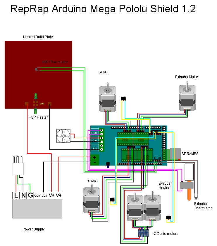
In general, all reprap electronics are broken down into 5 different areas:
The controller
The controller is the brains of the reprap. Almost all reprap controllers are based on the work of the Arduino microcontroller - and lately the ARM microcontroller. (The first generation RepRap used PICmicro) The software the microcontroller executes is called firmware.
While a lot of variations exist, they are exchangeable and basically all do the same thing. Sometimes the controller is a stand-alone circuit board with chips on it, sometimes the controller is an Arduino Mega with an add-on board (called a 'shield'). Find more at List of electronics.
Stepper Motors
A stepper motor is a type of electric motor that can be accurately controlled with the controller. Most repraps use 4 to 5 stepper motors. 3 to 4 motors control the x/y/z axis movement (sometimes the z axis is controlled by 2 motors) and 1 motor is used per extruder.
Stepper Drivers
A stepper driver is a chip that acts as a kind of middle-man between a stepper motor and the controller. It simplifies the signals that need to be sent to the stepper motor in order to get it to move.
Sometimes the stepper drivers are on separate circuit boards that are linked to the controller via cables.
Sometimes the stepper drivers are on small circuit boards that plug directly into the controller itself. In this case, the controller will have space for at least 4 of these small circuit boards (one for each stepper motor).
Finally, sometimes the stepper drivers are soldered right onto the controller itself.
End stops
An end stop is a very small and simple circuit board with a switch of some sort on it.
An end stop has two purposes:
- Calibrate printing limits at start up (Cartesian XYZ: the axis starts(/ends) ) (Delta printers: See Delta robot).
- Register when the tool head (e.g. an extruder) has moved too far in one direction and as an error trigger an endstop. The reason can e.g. be if the mechanics looses steps - or the steppers are not controlled correctly by the electronics or firmware. (A wrongly generated Gcode from a 3D-model, that tries to send the toolhead out of the print area, should result in an error generated by the firmware.)
Thus, there's normally 6 of these: 2 for each axis (Most firmware include software settings for max position, which allows for only the min position endstops to be required). A single end stop connects via wires to either:
- The controller.
- A stepper driver board.
Heated Bed
The print bed is what the RepRap extrudes plastic onto, where the plastic parts are built up.
While a heated bed is considered to be an optional component of a reprap, it often becomes a necessary and integral part of operating a RepRap over the long-term because, without a heated bed, parts have a tendency to cool down too quickly. This results in warping of corners (as the plastic shrinks while cooling) or the part physically detaching from the print bed too early, ruining the print.
Heated beds operate on the same principle as a kitchen toaster. They're just giant resistors with a temperature sensor. See also:
More Info
To see more details about reprap electronics, take a look at the List of electronics page.
Mechanical Body
When it comes to the mechanical body, it can be generally broken down into two parts:
- Movement along the x/y/z axes.
- The print bed
X/Y/Z Axis Motion
Main category page for Mechanical arrangement
When facing the front of a reprap, X axis movement is side to side, aka left to right movement, Y axis movement is forwards/backwards movement and Z axis movement is up and down along the vertical plane.
Linear movement is generally accomplished using one of 2 different methods:
- Belt/pulley driven motion.
- Threaded rod or leadscrew motion.
Belts and pulleys are good for fast/lightweight movement and threaded rods are good for slow but forceful movement. Most repraps use a combination of belts for X/Y axis movement and threaded rod for Z axis movement.
Belts and Pulleys
When it comes to accuracy, the most important part of your reprap is your belt/pulley combination. Current state of the art is the GT2 belt, along with a machined pulley that matches the exact bore size of your stepper motors (normally this is 5mm).
There are many types of belt/pulley combinations, currently (March 2012) most in use are:
- T5
- These are asynchronous metric timing belts. They have trapezoidal teeth and deliberate backlash to reduce belt wear and noise for uni-directional applications. They are difficult to get in North America. The pulleys themselves though can be printed. Using a printed pulley will give you approximately the same results as if you use an MXL pulley/belt combination with the wrong bore size.
- T2.5
- Like the T5 these are asynchronous metric belt/pulley combinations. These have a 2.5mm (.098") pitch and are printable. With the same diameter pulleys there is a better grip (compared to t5) on the belt and will give a better result. The best results are with metal pulleys due to the fine tooth profile.
- MXL
- This stands for "mini extra-light". These belts have been around since the 1940s. Like T5 & T2.5, these are also asynchronous timing belts but they are common in North America because they use imperial sizes. The distance between teeth is 0.08" and the teeth are trapezoidal. You *may* be able to find pulleys that have a 5mm bore but it seems difficult. Most stepper motors have spindles that are 5mm in diameter.
- HTD
- This stands for "high torque drive" and was introduced by Gates in 1971. These belts have less backlash than MXL and T5 belts because the teeth are deeper and are rounded. These belts were originally patented by Gates but the Patent has since expired.
- GT2
- These are Gates PowerGrip® GT®2 industrial synchronous timing belts. GT stands for "Gates Tooth". GT2 came about because the HTD patents ran out and they needed a new tooth profile that was not public domain. Gates says the GT2 belts will run OK on HTD pulleys but not the other way around. GT2 belts are stronger than HTD belts, but they need the GT2 tooth profile on the pulleys to achieve their ultimate strength advantage over HTD. These may be more difficult to find everywhere.
- Spectra
- Spectra fiber braided fishing line is quickly becoming a popular choice to replace belts in many applications after its first implementation in Tantillus and then in many Delta printers. It is cheap and available in most cities around the world. Once tightened correctly it has almost no backlash and provides very smooth movement due to the lack of bumpy teeth and its incredibly small bend radius allowing high steps per mm.
For more info see Choosing Belts and Pulleys.
Threaded rod
Most repraps use threaded rod for the Z axis. The Z axis doesn't have to move fast (but it is better if it can move quickly) because it generally only goes up tenths of a mm at a time. Threaded rod is ok for accuracy and force. Repraps don't require force but some CNC machines, use threaded rod for all 3 axes. Since the Z axis threaded rods support the weight of the x-carriage it's a good idea to use high-strength stainless steel for the rod and nut, otherwise they will suffer greater wear on the threads and experience premature failure.
Notes on Backlash
One thing to note about all ways of moving is backlash. Backlash is that jigglyness that you feel in both threaded rod and belts/pulleys when you change direction. This jigglyness/sloppiness affects accuracy.
The T5 and MXL belts above were originally designed to be used as timing belts. Timing belts normally only spin in one direction so backlash is not an issue. Thus, because the GT2 belts were designed to change direction, they will be more accurate.
The standard way of compensating for threaded rod backlash is to use 2 nuts and force them apart using a spring. This kind of makes sure that the nuts are always pushing against the threads so that when you change direction, it doesn't jiggle. Not sure if that makes sense but I'll leave it here anyways.
Print Bed
The print bed is what parts get printed on. The print bed may be stationary, like with the original reprap Darwin, or it may move along one of the x/y/z axes. Most repraps have the bed move along the Y axis but some will also move along the Z axis.
The bed usually consists of two plates: the upper plate and the lower plate.
Upper Plate
The upper plate is mounted to the lower plate on springs. The springs allow it to be levelled using adjusting screws. It also (I think) was designed this way because it gives a little if you accidentally ram the print head down into it.
The upper plate may or may not be heated. It's usually made of a PCB board or of metal. If the plate is heated, it will usually have a piece of glass held on top of it by bulldog clips.
Tape is usually applied to the upper plate to act as a print surface. It helps the extruded plastic stick to the bed and it also makes it easier to remove the part once it's done. The two most common tape types used are blue painter's tape and kapton tape.
Lower Plate
Sometimes the lower plate is called the frog plate because the original mendel's lower plate kind of looked like a frog.
It provides a sturdy base that the upper plate can be connected to. If the bed moves along one of the axes, then the lower plate is directly connected to the mechanism that moves the bed. For the Y axis, this usually means belts or for the Z axis, this usually means threaded rod.
Extruder
The extruder is responsible for feeding filament through a nozzle and melting it as it's deposited onto the bed where the part is made.
The extruder consists of two parts:
- The cold end
- The hot end
Normally, the "Cold End" is connected to the "Hot End" across a thermal break or insulator. This has to be rigid and accurate enough to reliably pass the filament from one side to the other, but still prevent much of the heat transfer. The materials of choice are usually PEEK plastic with PTFE liners or PTFE with stainless steel mechanical supports or a combination of all three.
However, there also exist Bowden Extruders which separate the hot end from the cold end by a long tube. Bowden extruders are much faster because they are much lighter.
Cold End
This can get a bit confusing here People tend to refer to the cold end as an "extruder" also. In reality, it's only half of the entire extruder mechanism. The cold end is the part that mechanically feeds material to the hot end, which in turn melts it.
Popular cold ends are:
Hot End
- See also Hot End Design Theory
The hot end is arguably the most complex aspect of 3d printers as it deals with the tricky business of melting and extruding plastic filament. In general, the hot end is a metal case with
- A resistor or heater cartridge that heats up so it melts the plastic (usually around 200C)
- A thermistor or a thermocouple which measures the temperature
The electronics basically monitor the temperature via the thermistor, then raise or lower the temperature by varying the amount of power supplied usually by some form of PWM
see Hotend comparison: Hot End Comparison and Hot End
Filament
Generally, people use one of two types of filament: ABS or PLA. ABS is strongly scented when melted and warps but is relatively strong whereas PLA is said to smell like waffles and is biodegradable. ABS fumes are detrimental to one's health. ABS will bend before it breaks whereas PLA is relatively brittle. Consequently, for delicate structural roles, PLA should be used, however, for other purposes, ABS can be ideal.
Notes on PID
Sometimes you will hear people talk about PID when discussing extruders. PID is a closed-loop control algorithm that engineers have been using for years. It is a mathematical algorithm that uses feedback from sensors (measuring temperature, for example) and controls an output (such as switching a heater on and off) to reach and maintain the desired setpoint (the temperature you want the extruder to have, for example).
Real world example: When you are driving your car down the highway, you're doing your own PID-like function as you watch the road and adjust the steering wheel to stay in your lane. If you adjust a little bit at a time and often enough, you stay in your lane nicely. But if you wait until you hit the lines on either side of the road before adjusting the wheel, people will think you're drunk and you'll oscillate all over the road. You may still get where you're going but it won't be pretty. PIDs use constants (numbers) that have to be tuned (adjusted) to the application. To continue the driving example, drunk is having bad constants, sober is just the right numbers.
Cruise control in a car is another good example of an every day PID controller.