RAMPS 1.4/kr
작성 중이기 때문에 영문판을 병기하고 있습니다.
|
English • العربية • български • català • čeština • Deutsch • Ελληνικά • español • فارسی • français • hrvatski • magyar • italiano • română • 日本語 • 한국어 • lietuvių • Nederlands • norsk • polski • português • русский • Türkçe • українська • 中文(中国大陆) • 中文(台灣) • עברית • azərbaycanca • |
Release status: unknown

| Description | RepRap Arduino Mega Pololu Shield
Arduino MEGA 기반 modular RepRap electronics.
|
| License | unknown
|
| Author | [[User:{{{author}}}]]
|
| Contributors | |
| Based-on | |
| Categories | |
| CAD Models | |
| External Link |
Contents
- 1 개요
- 2 안전 유의사항
- 3 열 설계 결함!?
- 4 조립
- 4.1 부품 납땜
- 4.2 필요한 도구들
- 4.2.1 Shield 조립
- 4.2.1.1 C2 - 100nF 캐패시터
- 4.2.1.2 LED1 - 녹색 LED
- 4.2.1.3 LED2, LED3, LED4 - 적색 LED
- 4.2.1.4 R13, R14, R15 - 10 Ohm resistor
- 4.2.1.5 R12 - 1K 저항
- 4.2.1.6 R23, R24, R25 - 1.8K 저항
- 4.2.1.7 R1, R7, R11, R21, R22 - 4.7K 저항
- 4.2.1.8 R16, R17, R18, R19, R20 - 10K 저항
- 4.2.1.9 R2, R3, R4, R5, R6, R8, R9, R10 - 100K 저항
- 4.2.1.10 C1, C5, C8 - 10uF 캐패시터
- 4.2.1.11 C3, C4, C6, C7, C9, C10 - 100uF 캐패시터
- 4.2.1.12 리플로우 작업
- 4.2.1.13 Top pins
- 4.2.1.14 Driver sockets
- 4.2.1.15 D1, D2 - 다이오드
- 4.2.1.16 F1 - MFR500 퓨즈
- 4.2.1.17 Bottom pins
- 4.2.1.18 리셋 스위치
- 4.2.1.19 Mosfet Terminal
- 4.2.1.20 Power Terminal
- 4.2.1.21 Q1, Q2, Q3 - Mosfets
- 4.2.1.22 F2 - MFR1100 Fuse
- 4.2.1.23 Inspection
- 4.2.2 스텝 모터 제어보드
- 4.2.3 Opto Endstops
- 4.2.4 기계식 Endstops
- 4.2.5 모터 선에 커넥터 연결하기
- 4.2.6 써미스터 결선
- 4.2.7 Pololu carriage
- 4.2.1 Shield 조립
- 5 최종 작업
- 6 펌웨어/핀 배치
개요
이제 RAMPS 1.4는 더 많은 수동 소자를 넣기 위해 저항과 축전기를 표면 실장하고 있습니다. 이것은 스테핑 모터를 더 많이 제어할 수 있게 하기 위한 조치이지만, but we stuck with larger sizes to make it fairly painless.


안전 유의사항
가지고 계신 RepRap에 전원을 인가할 때(12볼트의 전압을 넣어줄 때) 화재를 방지하기 위한 몇 가지의 일반적인 주의사항을 숙지하고 있어야 합니다. 이런 경우의 문제를 조기에 탐지하기 위하여, 연기 감지기를 사용해 보시는 건 어떨까요? 만약 가지고 계시지 않다면. 하나 사 보시는 것을 추천합니다!
열 설계 결함!?
문제가 되는 부분:
- 베드의 모스펫이 너무 뜨겁습니다!!!
- 만약 당신의 히트베드가 11A와 가깝거나 바로 위라면, polyfuse 는 매위 뜨겁게 될 것입니다.
- key solder-pads 주위는 너무 얇게 연결되어 있습니다.
조립
부품 납땜
필요한 도구들
You must have: 인두기, 납, good tweezers You really need: 솔더 윅, 납 흡입기, 플럭스 펜 Optional methods use: 페이스트, 핫 플레이트 혹은 오븐
Shield 조립

RAMPS 1.4를 납땜하는 과정에는 Surface mount와 Through-hole 납땜이 포함되어 있습니다.
The surface mount can be done a few ways. RAMPS 보드의 모든 SMT 부품들이 큰 2패드 파츠이기 때문에 you can do pin by pin soldering pretty easy with normal soldering equipment. Start by putting a small amount of solder on one pad. If you have flux, coat the soldered pad. Use the tweezers to hold the component down in position and heat the solder to tack the component into place (make sure the entire solder blob flows so you don't get a cold solder). Then solder the other pad. Also popular is using solder paste for pad by pad soldering, Oven Reflow (need link), and HotplateReflowTechnique
먼저 SMT 부품들을 납땜하세요. Then the PTH on top of the board. 마지막으로 핀헤더들을 하부에 납땜하세요.
C2 - 100nF 캐패시터

This can be placed in any orientation.
LED1 - 녹색 LED

Place these with the end having green dots away from the + mark on the PCB.
LED2, LED3, LED4 - 적색 LED

Place these with the end having green dots away from the + mark on the PCB.
R13, R14, R15 - 10 Ohm resistor

These can be placed in any orientation.
R12 - 1K 저항

These can be placed in any orientation.
R23, R24, R25 - 1.8K 저항

These are marked 1K on the PCB, but we are using larger ones to accommodate higher voltages. These can be placed in any orientation.
R1, R7, R11, R21, R22 - 4.7K 저항

저항은 극성과 상관없이 납땜할 수 있습니다.
R16, R17, R18, R19, R20 - 10K 저항

저항은 극성과 상관없이 납땜할 수 있습니다.
R2, R3, R4, R5, R6, R8, R9, R10 - 100K 저항

저항은 극성과 상관없이 납땜할 수 있습니다.
C1, C5, C8 - 10uF 캐패시터

These must be placed in the proper orientation. The board has the foot print of the components printed on it. The rounded corners on the base of the capacitor must line up with the white print on the PCB.
C3, C4, C6, C7, C9, C10 - 100uF 캐패시터

These must be placed in the proper orientation. The board has the foot print of the components printed on it. The rounded corners on the base of the capacitor must line up with the white print on the PCB.
리플로우 작업


If you are doing oven or hot plate method, now is the time apply heat (add links here). 만약 인두기를 사용하신다면, you have probably already soldered all these components.
Make sure to inspect the SMT soldering at this point since it will be harder to rework after the headers are on top.
Top pins

Solder 1 1x6, 6 1x4, and 7 2x3 pin headers on top of the board. The long post should be standing up to take a connector. Solder one leg on each one to tack them into place. Then re-heat the joint and push on the component until it is perfectly situated. Then you'll want to solder the rest of the leads. You will get burnt if you touch the other side of the pin you are soldering.
If you want to use the extra pin outputs, now is the time to solder on the rest of the headers.
Driver sockets

Place the female headers for the stepper drivers on top of the board. You can use the 1x8 and 1x6 pin headers to jig them straight. Turn the board over and solder these pins.
D1, D2 - 다이오드


These must be placed in the proper orientation. The band on the diode must be turned the same way as the mark on the board.
Definitely solder D2 in. D2, F1, and F2 are shown installed here.
D1 should only be installed if the 5A rail is powered by 12V. It can be omitted and the Arduino will be powered from USB. You will want D1 installed if you add components to print without a PC. To reiterate, D1 MUST be omitted if you are powering the 5A rail by more than 12V, or the power is not absolutely clean, otherwise you may damage your ramps.
F1 - MFR500 퓨즈
This is the smaller yellow fuse. This can be placed in any orientation. When soldering the fuses it is best to use a piece of 3mm filament or something similar to keep the ceramic coating on the pins from blocking proper solder along the through hole.
Since the fuses are the tallest parts, it is simpler and more convenient to solder them last. From this point on, solder the rest of the RAMPS in order of bottom pins, reset switch, terminals, mosfets and then fuses.
Bottom pins


Place these on the bottom of the board with the long post out to plug into the Arduino MEGA. You can plug them into the MEGA to hold them in place while you solder. Do not overheat the pins while in Arduino or you may damage its connectors.
리셋 스위치

This can only be oriented in one direction.
Mosfet Terminal


This must be oriented where the wire holes are turned towards the edge of the board. Solder a pin on each end and make sure the component is flat on the board and solder the middle pins.
Power Terminal

This can only be oriented in one direction.
Q1, Q2, Q3 - Mosfets

These must be orientated as in the picture. The tall heat sink part of the mosfet needs to be turned the same as the mark on the board.
F2 - MFR1100 Fuse
This is the larger yellow fuse. This can be placed in any orientation.
Inspection
Inspect your work. Clean any solder bridges and suspect solders.
스텝 모터 제어보드
- Jumpers need to be installed under each stepper driver:
 점퍼   Yes/No     step size
 1     2    3
 no   no    no    full step
 yes  no    no    half step
 no   yes   no    1/4 step
 yes  yes   no    1/8 step
 yes  yes   yes   1/16 step
For now the default is 1/16 micro stepping (all jumpers installed under drivers)
- Cut the pin headers to 8 pins long so that they fit each side of the stepper driver.
- Insert the pin headers into the sockets on RAMPS
- Fit the stepper drivers onto the pin headers and solder. Only heat each pin for a few seconds at time to avoid damage to the socket.
Opto Endstops
Opto endstop build instructions can be found at Gen7_Endstop_1.3.1, and also [here] for reprapsource.com's instructions.
- Cut the 26awg 3 conductor cable into 3 length.
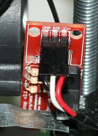
- Note: you may want to wait until you've built your machine to cut the cables to the perfect length.
- crimp and solder a female connector to the ends of each wire. (solder not necessary with proper crimp tools)
- use the 2.54mm 1x3 housing.
- Connect at least the minimum endstops.
- Cut the 26awg 3 conductor cable into 3 length.


| RAMPS End | |
| SIG (S) | White |
| GND (-) | Black |
| VCC (+) | Red |
| Endstop End | |
| VCC (+) | Red |
| SIG (S) | White |
| GND (-) | Black |
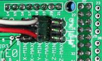
기계식 Endstops

The recommended firmware will provide a configuration to use mechanical endstops with just two wires.
Find the area labelled "endstops" in the upper right corner of the board and for each of the X, Y, and Z pairs of pins (label should be below each set) do the following:
- Connect S (top row, labelled to the left) on RAMPS to NC on the switch.
- Connect GND on RAMPS to C on the switch.
Note: The latest firmware such as Marlin seems to use NO as the default pin on the switch. Otherwise you may need to invert the endstops in the firmware. You can use M119 to check your endstops status.
모터 선에 커넥터 연결하기
- Female 커넥터를 각각의 선 끝에 납땜합니다.
- 2.54mm 1x3 커넥터를 이용합니다.
- 예시는 RC 등에 사용되는 타입입니다. 모터에 대한 자세한 정보는 Stepper Motors를 참고하십시오.
써미스터 결선
0.1" 2핀 커넥터를 사용하여 선을 마무리합니다.
- Connect the cable so the 2 wires go to T0
- Connect the 2 heater wires to D10 (E0H on older boards) and the + connection above it.
- If changing to an unverified firmware it is best to verify heater circuit function with a meter before connecting heater to prevent damage to the extruder.
Pololu carriage

This section assumes you are using Pololu, but there are other options. Insert two 1x8 pin headers into the board. If you bought a kit with one 16 pin header, 그냥 잘라서 1*8 핀헤더 두개로 만들면 됩니다. Make sure that the side with the labels has the long ends of the posts, and the side you want to solder is the side with the heat sink. Doing this backwards will cause you not to see the labels and will most likely not fit. Remember to apply a heat-sink to the largest chip on the back.
최종 작업
Pre-Flight Check
If you think you may have mistakes you can install only one stepper driver during initial testing and risk only one stepper driver.
The trimpot on the stepper drivers controls the current limit. Turn it all the way down (counter clock wise) and back up 25%. Be careful to not force the trimpot, it is delicate. You will need to fine tune the current limit later. Note that it is allways giving the motors that much power, even when not moving, so if your stepper motor drivers are getting hot, you may want to turn it down slightly.
[Connect the minimum endstops] for X,Y, and Z
Connect Motors (전원이 인가되었을 때 모터를 연결하거나 빼지 마세요. this will cause the motors to spazz and possibly kill your stepper driver.)
You may want to use this [code] to test all the electronics before installing any of the suggested firmwares. 펌웨어를 설치합니다(상세한 내용은 아래 참고). 펌웨어 설치는 12V 전원 없이도 USB 연결만으로 가능합니다.
결선
RAMPS를 결선하는 것은 비교적 쉬운 편입니다. 그저 익스트루더의 열선을 D10에 연결하고, 써미스터는 우측 중간에 있는 T0 핀에, 그리고 스테핑 모터와 엔드스탑을 결선하면 끝납니다. 왼쪽부터 오른쪽까지 순서대로, 모든 스테핑 모터의 선을 적색, 청색, 녹색, 검은색 혹은 적색, 녹색, 황색, 청색 순으로 Pololu Carriage 옆에 연결합니다, blue into the pins next to the Pololus. When you connect the wires to the endstops (엔드스탑을 3개 사용하면, plug them into the MIN (-) slots), make sure you match the labels.

참고로 Tesla & Tonok 펌웨어는 D9를 이용하고 and Sprinter, Marlin, 그리고 Johnny/Tonok 펌웨어는 D10을 핫엔드용으로 사용합니다.
경고
Reversing +/- or otherwise incorrectly connecting power can destroy your electronics and cause fire hazard.
올바르지 않게 스테핑 모터 제어보드를 삽입하면 회로를 망가뜨리고 화재를 일으킬 수 있습니다. 항상 제어보드를 제거하거나 조정할 때 USB 연결이 끊어져 있는지 확인하세요. 항상 보드를 정확한 방향과 소켓에 올바르게 삽입하시기 바랍니다.
엔드스탑의 핀 배치는 Signal - GND - VCC 혹은 VCC - Sig - GND like the rest of RepRaps boards. Make sure to wire them correctly. This is done to allow squeezing fatter traces on the printable board.
전원 인가
12V 파워 서플라이를 RAMPS 쉴드에 연결하십시오. +/- 극성을 반대로 연결하거나 그 밖의 잘못된 전원 연결은 당신의 보드를 망가뜨리거나 화재를 불러일으킬 수 있습니다..
The bottom pair of connectors marked 5A power the stepper drivers and Extruder heater/fan (D9, D10). The source should be rated a minimum of 5A.
The pair of connectors above marked 11A power a Heated Bed, or other output (D8). The source should be rated a minimum 11A (if both power rails are connected to the same supply it should have a minimum rating of 16A).
The barrel connector, on the Arduino MEGA, will NOT power RAMPS and will not provide power to the stepper motors, heated bed, etc.
The power connector plug may not be obviously labeled, looking at the power connection the positive is on the left and the negative is on the right of the plug.
Power Supply
RAMPS is quite happy with the 12 V line from PCPowerSupply. Or you can hack up a 12V laptop power supply, or other 12 V "wall wart" power supply. Be sure that the power can output 5A or greater. Additional 11A may be needed for heated bed support.
See Connecting power above.
The 3 pins next to the reset switch are meant to optionally connect to your PSU.
The PS_ON pin is intended to switch your power supply on and off. Many firmwares support pulling this pin low with M80 command to turn the power supply on, and M81 to turn it off. This behavior is desired for ATX power supplies and can be modified in firmware to support 5V high power supplies like those borrowed from an Xbox.
Without D1 installed, or when the 12VIN is not connected, the Arduino gets its power from USB. If you want your kit powered without USB connected you need to solder in D1 OR connect VCC to your PSU.
The VCC pin can be connected to your ATX's 5Vsb to continuously power the Arduino from your ATX power supply. You will want to make sure that D1 is not installed or cut out. The Arduino is not designed to be powered directly on the VCC rail and the VIN pin at the same time.
The 5V pin in that connector on RAMPS only supplies the 5V to the auxiliary servo connectors. It is designed so that you can jumper it to the VCC pin and use the Arduino's power supply to supply 5V for extra servos if you are only powered from USB or 5V. Since there is not a lot of extra power from the Arduino's power supply you can connect it directly to your 5V power supply if you have one. You can also leave this pin not connected if you have no plan to add extra servos.
최대 입력 허용 전압
Power Supply without diode
RAMPS에 파워 서플라이를 연결하기 위해서는 3개의 고려해야 할 요소가 있습니다:
- 아두이노 메가의 최대 입력 허용 전압
- 평활용 캐패시터의 최대 입력 허용 전압
- PTC 퓨즈의 최대 입력 허용 전압
첫번째로, 1N4004 다이오드를 connects the RAMPS input voltage to the Arduino Mega which has a recommended maximum input voltage of 12 volts. If your board does not have this diode soldered in (or if you cut it), you will need to power the Mega through the USB connector or through a separate 5v line, but this allows a higher RAMPS voltage.
두번째로, most boards use 25v or 35v aluminum electrolytic capactors (C2, C3, C4, C6, C7, C9, and C10). To be safe, you should only go to half of your rated maximum voltage -- thus if your board has 35v capacitors (code VZA) then you should use a maximum input of 17.5v. The absolute maximum voltage is determined by the pololu servo drivers, which themselves are limited to 35V.
세번째로, the MF-R500 (5A) PTC fuse is rated to 30V and the MF-R1100 (11A) PTC fuse is rated to 16V. They will need to be replaced with real fuses.
Power Supply with diode
If your board has a 1N4004 diode soldered in, do not apply more than 12 V to it. Original flavor Arduino Mega are rated to 12 V input. While Arduino Mega 2560 can take 20 V, it is not recommended.
펌웨어/핀 배치
RAMPS 1.4 uses the same pin definitions as 1.3.
You will need the Arduino software at to upload the firmware to Arduino Mega. The version of Arduino you need may be determined by the firmware you want to use. The current (as of 2014-01-22) Marlin firmware is compatible with Arduino version 1.0.5. Some other firmwares may require Arduino software version 0023, NOT the most recent version. Please see your firmware documentations if you need assistance.
문제 해결: You may need to make sure that the driver is installed for the Arduino MEGA by going to Control Panel -> Hardware and Sound -> Device Manager. If the device that appears/disappears when you plug in and unplug the board USB is "Unknown Device" under "Other devices", then you need to right click on the device and click the update driver button. Find where on your computer you saved/installed the Arduino software, and tell the wizard to search in the driver folder there. Windows 8 will give this error: "The third party INF does not contain digital signature". If so, save the zip for the latest version of Arduino on your PC, and repeat the steps above with the driver folder in there. It should contain the digital signature Windows needs.
Sprinter and Marlin are popular and stable firmwares for RAMPS as of 3/28/2012. Pronterface is a cross platform printer control program that can be used for testing/printing.
Working preconfigured Sprinter firmware can be downloaded at . Mechanical is in the folder ending with ME, optical endstop firmware is in the folder ending in OE.
Working preconfigured Marlin firmware can be downloaded at . is for mecanical endstops, for optical endstop need to reverse the logic of endstops from the configuration.h shell, the language of display is in italian, but can easy be canged from the shell language.h, it is preconfigured for the RepRapDiscount Smart Controller and similar LCD module. You will need to disable LCD in configuration.h if not using it.
Others (Need pins set in Firmware as below):
- mechanical endstops (now the default ultimachine.com option) require #define OPTO_PULLUPS_INTERNAL 1 to be added to configuration.h if not there by default.
Here are the pin definitions for this board.
// For RAMPS 1.4
#define X_STEP_PIN         54
#define X_DIR_PIN          55
#define X_ENABLE_PIN       38
#define X_MIN_PIN           3
#define X_MAX_PIN           2

#define Y_STEP_PIN         60
#define Y_DIR_PIN          61
#define Y_ENABLE_PIN       56
#define Y_MIN_PIN          14
#define Y_MAX_PIN          15

#define Z_STEP_PIN         46
#define Z_DIR_PIN          48
#define Z_ENABLE_PIN       62
#define Z_MIN_PIN          18
#define Z_MAX_PIN          19

#define E_STEP_PIN         26
#define E_DIR_PIN          28
#define E_ENABLE_PIN       24

#define SDPOWER            -1
#define SDSS               53
#define LED_PIN            13

#define FAN_PIN            9

#define PS_ON_PIN          12
#define KILL_PIN           -1

#define HEATER_0_PIN       10
#define HEATER_1_PIN       8
#define TEMP_0_PIN          13   // ANALOG NUMBERING
#define TEMP_1_PIN          14   // ANALOG NUMBERING
블루투스 모듈 결선하기
RAMPS 보드와 아두이노 메가 보드의 UART 신호 레벨은 5V이지만, 블루투스 모듈은 3.3V 레벨만을 지원합니다. 그러므로 TxD 포트의 전압은 반드시 저항으로 분압되어야 합니다. 이 수동적인 방법은 디지털 방식을 사용하지 않고도 115K Baud에서는 꽤 쓸만한 편입니다. 총 4 포트만 결선하면 됩니다.

블루투스로 통신하기
블루투스 모듈을 제대로 설치하였다면 PC나 노트북 등에서 블루투스 기기를 검색하고 페어링한 다음 기존에 쓰던 대로 통신하여 사용할 수 있습니다.
구매 방법
Where to buy RAMPS를 참고하세요.