RAMPS 1.3
|
English • العربية • български • català • čeština • Deutsch • Ελληνικά • español • فارسی • français • hrvatski • magyar • italiano • română • 日本語 • 한국어 • lietuvių • Nederlands • norsk • polski • português • русский • Türkçe • українська • 中文(中国大陆) • 中文(台灣) • עברית • azərbaycanca • |
Release status: Working

| Description | RepRap Arduino Mega Pololu Shield
Arduino MEGA based modular RepRap electronics.
|
| License | |
| Author | |
| Contributors | |
| Based-on | |
| Categories | |
| CAD Models | |
| External Link |
Contents
Summary
This page has been copied from v1.2 so there may be a couple discrepancies while it is finished.
RepRap Arduino Mega Pololu Shield, or RAMPS for short. It is designed to fit the entire electronics needed for a RepRap in one small package for low cost. RAMPS interfaces an Arduino MEGA with the powerful Arduino MEGA platform and has plenty of room for expansion. The modular design includes plug-in stepper drivers and extruder control electronics on an Arduino MEGA shield for easy service, part replacement, upgrade-ability and expansion. Additionally as long as the main RAMPS board is kept to the top of the stack a number of Arduino expansion boards can be added to the system.
As of version 1.3, and in order to fit more stuff, RAMPS is no longer designed for easy circuit home etching. If you want to etch your own PCB either get version 1.25 or Generation_7_Electronics. Version 1.25 and earlier are "1.5 layer" designed boards (i.e. it's double sided board, but one of layers can easily be replaced with wire-jumpers) that is printable on your RepRap with the etch resist pen method, or home fabbed with toner transfer.
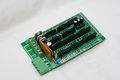
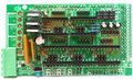
Top of RAMPS 1.3


Safety Tip
Once you start putting electricity into your RepRap - even at just 12 volts - you have to take basic, common sense precautions to avoid fires. Just in case these fail, test your workshop smoke detector. Got no smoke detector? Get one!
Assembly
Component Soldering
Shield Assembly
Beginning solderers may find the task much easier if they were to work from the inside of the board to the outside, rather than using the current order below.- Resistors as shown to the right.
- Small 100nF capacitor, C4 (yellow)
- LED - Positive(long lead) at the top, ground (Short lead) at the bottom.
- D2 1N4004 the diode just above the reset button. Make sure the stripe is oriented the same as the silkscreen on the board.
- Place the 2x3 male pin headers on top of the board, 8 of them needed. These are for microstep selection jumpers, and endstop jacks. It is easiest to place all these and hold them in place with a card to flip board for soldering. Make sure the tail (short side) of the pins goes into your board. Also, make sure the endstop pins are actually in the endstop holes and not shifted one hole to the right in the I2C pads.
- Solder 6x1 male pins header in the T0, T1, & T2 holes for thermistor jack. Solder one of the end pins first, straighten the pins to be perpendicular to the board and solder the rest of the pins.
- Solder 1x4 male pin headers for the motor connectors. You need to put these in the 4 pads next to X,Y,Z,E0, & E1. If your bot uses 2 motors on Z axis put 2 sets on Z (else you can just use 1 on Z).
- Two 1x24 socket headers into place for the X,Y, and Z stepper driver sockets.
- (4) 1x8 socket headers into place for the E0 & E1 stepper driver sockets.
- Solder the large capacitors, C4, the 100nF capacitor, C5,C8 10uF capacitor as shown lower right.
- They must be inserted in the correct orientation. + to the bottom for C4 and C5 or left for C8.
- Mosfets, Q1,Q2,Q3, the three N-channel mosfet, STP55NF06L (these can be made nice and straight by soldering one pin on each mosfet, straightening component, then soldering other pins)
- They must be oriented in correctly (as per photographs)
- The big yellow MF-R500 fuse (F1) and bigger yellow MF-R1100 fuse (F2).
- Power connector, X1, the 4 pin fixed/pluggable terminal block.
- Screw terminal block, (6 pin)
- Pass-through headers that will connect the shield to the Arduino board (around the perimeter of the board). This includes the (1) 2 x 18 Pin Stackable Female Header, the (5) 1 x 8 Pin Stackable Female Header and the (1) 1 x 6 Pin Stackable Female Header.
- More recent kits include 2x18, 1x22, and 1x24 pin headers for connection to the Arduino MEGA. Cut the 1x24 headers into (1) 1x6 + (5) 1x8 lengths. If you insert these into the Arduino MEGA to hold them straight while soldering, take care not to heat for too long risking melting the Arduino's connector.
- You can omit D1, the 1N4004 diode. The diode can be omitted, although it may be needed in the future for printing from SD or USB. This will power the Arduino from the shield's 12V input. All diodes must be oriented correctly.
If you are using higher than 12V to power the shield you should omit the diode to prevent damage to the Arduino and the logic sides of the stepper drivers.Warning: The high side of the stepper boards are designed to accept up to 35V, but if you do this the heater and other high side outputs will be at that voltage also. You may need to adjust the heater resistance, etc.
- Reset switch, S1, push button switch
- Thoroughly check for shorts (This is crucially crucial for DIY etched boards.)
- Check for continuity between each and every pin to the pins next to them and GND, 12V, 5V (VCC).
- Set your meter to beep for continuity, hold a probe on GND and check all soldered pins. If it beeps check if it is supposed to be GND and contine. Repeat for 12V and 5V.
Stepper Driver Boards
- Jumpers need to be installed under each stepper driver:
 jumper   Yes/No  step size
 1     2    3
 no   no    no    full step
 yes  no    no    half step
 no   yes   no    1/4 step
 yes  yes   no    1/8 step
 yes  yes   yes   1/16 step
For now the default is 1/16 micro stepping (all jumpers installed under drivers)
- Cut the pin headers to 8 pins long so that they fit each side of the stepper driver.
- Insert the pin headers into the sockets on RAMPS
- Fit the stepper drivers onto the pin headers and solder. Only heat each pin for a few seconds at time to avoid damage to the socket.

Opto Endstops
- Cut the 26awg 3 conductor cable into 3 length.

- Note: you may want until you've built your machine to cut the cables to the perfect length.
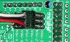
- WARNING In order to keep the PCB at a printable resolution two wires have been flipped from the traditional opto endstop boards. The signal pin has been moved to the outside of the connector.
- Hooking these up incorrectly can damage the components.
- crimp and solder a female connector to the ends of each wire. (solder not necessary with proper crimp tools)
- use the 2.54mm 1x3 housing.
- Connect at least the minimum endstops.
- Cut the 26awg 3 conductor cable into 3 length.


| RAMPS End | |
| SIG (S) | White |
| GND (-) | Black |
| VCC (+) | Red |
| Endstop End | |
| VCC (+) | Red |
| SIG (S) | White |
| GND (-) | Black |
Mechanical Endstops
The recommended firmwares provide a configuration to use mechanical endstops with just these two wires.
Connect GND on RAMPS to C on the switch. Connect S on RAMPS to NC on the switch.
Put the connectors on the motor wires
- solder a female connector to the ends of each wire.
- use the 2.54mm 1x3 housing.
- Shown is the type used for servos in RC projects. See Stepper Motors for info on motors.
Thermistor Wires
Use a 2 pin 0.1" connector to terminate the thermistor wires.
- Connect the cable so the 2 wires go to T0
- Connect the 2 heater wires to D10 (E0H on older boards) and the + connection above it.
- If changing to an unverified firmware it is best to verify heater circuit function with a meter before connecting heater to prevent damage to the extruder.
Final Setup
Wiring
It is relatively simple to wire up the RAMPS. Just add the extruder heating coil wire to D10, the thermistor to the two T0 pins on middle right right, and wire up the steppers and endstops. From left to right, wire all of the stepper motor's wires as red, blue, green, and black or red, green, yellow, blue into the pins next to the Pololus. When you connect the wires to the endstops (if you are using 3 endstops, plug them into the MIN (-) slots), make sure you match the labels.

Pre-Flight Check
If you think you may have mistakes you can install only one stepper driver during initial testing and risk only one stepper driver.
The trimpot on the stepper drivers controls the current limit. Turn it all the way down (counter clock wise) and back up 25%. Be careful to not force the trimpot, it is delicate. You will need to fine tune the current limit later. Note that it is allways giving the motors that much power, even when not moving, so if your stepper motor drivers are getting hot, you may want to turn it down slightly.
Connect the minimum endstops for X,Y, and Z
Connect Motors (Do not disconnect or connect motors while powered; if the connection is loose, this will cause the motors to spazz and possibly kill your stepper driver.)
Install firmware (More info below). Firmware flashing can be done without 12V power supply connected.
Warnings
Reversing +/- or otherwise incorrectly connecting power can destroy your electronics and cause fire hazard.
Incorrectly inserting stepper drivers will destroy your electronics and cause a fire risk. Always make sure power and USB is disconnected when removing or adjusting stepper drivers. Always make sure to insert drivers in correct orientation and in the socket correctly.
The endstop pins are Signal - GND - VCC, instead of the VCC - Sig - GND like the rest of RepRaps boards. Make sure to wire them correctly. This is done to allow squeezing fatter traces on the printable board.
Connecting Power

Connect your 12V power supply to the RAMPS shield.Reversing +/- or otherwise incorrectly connecting power can destroy your electronics and cause fire hazard
The bottom pair of connectors marked 5A power the stepper drivers and Extruder heater/fan (D9,D10). The power supplied to these should be rated a minimum of 5A.
The pair of connectors above marked 11A power a Heated Bed, or other output (D11). The power supplied here should be rated a minimum 11A. (If both power rails are connected to the same supply it should have a minimum rating of 16A)
The barrel connector (DC power input) on the Arduino MEGA itself is not used for our application.
The power connector plug may not be obviously labeled, looking at the power connection the positive is on the left and the negative is on the right of the plug.
Power Supply
RAMPS 1.3 uses RAMPS is quite happy with the 12 V line from PCPowerSupply. Or you can hack up a 12V laptop power supply, or other 12 V "wall wart" power supply. Be sure that the power can output 5A or greater. Additional 11A may be needed for heated bed support.
See Connecting power above.
Maximum Input Voltage
Power Supply without diode
The 1N4004 diode connects the RAMPS input voltage to the MEGA. If your board does not have this diode soldered in, you can safely input as much as 35V. (The pololus can do up to 35V)
Power Supply with diode
If your board has a 1N4004 diode soldered in, do not apply more than 12 V to it. Original flavor Arduino Mega are rated to 12 V input. While Arduino Mega 2560 can take 20 V, it is not recommended.
Final Check

Note that tesla & tonok firmware use d9 and sprinter and johnny/tonok use d10 for the extruder hot end.
Firmware and Pin Assignments
You will need the Arduino software at http://www.arduino.cc/en/Main/Software to upload the firmware to Arduino Mega.
Working preconfigured firmwares are available at:
In Active Development: (Need pins set in firmware as below)
Marlin - Derived from Sprinter and Grbl by Erik van der Zalm. It supports printing from an SD card, up to two extruders and a heatbed. Marlin employs Look Ahead processing to give improved quality and faster cornering. It also employs PID control over the hot end. It works well with Pronterface software or alternately you can attach a LCD and rotary encoder and use your printer independently of a computer. (Schematic available at Justblairs)
Sprinter - This is a firmware for RAMPS and other reprap single-processor electronics setups. It supports printing from SD card, active heatbed control, and ATmega internal pullups.
Sjfw - This firmware includes some portions which are copped directly from the MBI firmware, and some code that is based on code in the Sprinter and Teacup firmwares, and one large option taken from Marlin firmware. It supports printing from SD card, Look Ahead and printing from SD. Like Marlin you can also attach a LCD based control panel to using this firmware
Older: (Need pins set in firmware as below)
https://github.com/tesla893/Tonokip-Firmware - Tesla893's Tonokip-Firmware fork, works w/ RepSnapper and Skeinforge - Added Features over original Tonokip but not as up to date as Klimentkip
https://github.com/kliment/Klimentkip - Kliment's Tonokip-Firmware Fork with Acceleration, PID, SD support, and other goodies - Updated frequently, with many active developers/hackers/users.
https://github.com/johnnyr/Tonokip-Firmware works excellently with RepSnapper and Skeinforge - Not as current
https://github.com/ramps/FiveD_for_RAMPS_GCode_Interpreter for use with Host Software or ReplicatorG or RepSnapper
- mechanical endstops (now the default ultimachine.com option) require #define OPTO_PULLUPS_INTERNAL 1 to be added to configuration.h
There are predefined pins for FiveD_on_Arduino in git master, but support is experimental. Programming works following the instructions in the wikipage.
Here are the pin definitions for this board.
// For RAMPS 1.3
#define X_STEP_PIN         54
#define X_DIR_PIN          55
#define X_ENABLE_PIN       38
#define X_MIN_PIN           3
#define X_MAX_PIN           2

#define Y_STEP_PIN         60
#define Y_DIR_PIN          61
#define Y_ENABLE_PIN       56
#define Y_MIN_PIN          14
#define Y_MAX_PIN          15

#define Z_STEP_PIN         46
#define Z_DIR_PIN          48
#define Z_ENABLE_PIN       62
#define Z_MIN_PIN          18
#define Z_MAX_PIN          19

#define E_STEP_PIN         26
#define E_DIR_PIN          28
#define E_ENABLE_PIN       24

#define SDPOWER            -1
#define SDSS               53
#define LED_PIN            13

#define FAN_PIN            9

#define PS_ON_PIN          12
#define KILL_PIN           -1

#define HEATER_0_PIN       10
#define HEATER_1_PIN       8
#define TEMP_0_PIN          13   // ANALOG NUMBERING
#define TEMP_1_PIN          14   // ANALOG NUMBERING
Source
| FILE ID# | TYPE | DESCRIPTION | DOWNLOAD |
|---|---|---|---|
| File:ArduinoMegaPololuShield.zip | Eagle Files | These are the files you need to make the board.(Use the File: link to the left to access older versions of the file.) | media:ArduinoMegaPololuShield.zip |
| File:RepRapjr.lbr | Eagle Libraries | The components used in this board are here. see Eagle_Library | media:RepRapjr.lbr |
Bill of Materials
| ID | Description | Quantity | Part Number | Reichelt Order Number | Digikey Part Number (Description) |
|---|---|---|---|---|---|
| U1 | Arduino Mega | 1 | 2560 or 1280 | N/A | |
| U2,U3,U4,U5 | Pololu stepper driver board | 4 | A fifth one can be used for a 2nd extruder or extra axis | N/A | |
| C4 | 100nF capacitor (> highest planned voltage) | 1 | X7R-2,5 100N (verified) | 445-5303-ND (CAP CER 0.10UF 50V X7R RAD) | |
| C1,C5,C8 | 10uF capacitor (>5V) | 3 | RAD 10/35 (verified) | 445-5339-ND (CAP CER 10UF 10V X5R RAD) | |
| C6 | 100uF capacitor (> highest planned voltage) | 1 | RAD 100/25 (verified) | P5182-ND (CAP ALUM 100UF 50V 20% RADIAL) | |
| R1,R7,R11 | 4.7K resistor (250mW 1%) | 3 | METALL 4.70K | S4.7KCACT-ND (RES MF 1/4W 4.7K OHM 1% AXIAL) | |
| R2,R3,R4,R5,R6,R8,R9,R10 | 100K resistor (250mW) | 8 | 1/4W 100K | CF14JT100KCT-ND (RES 100K OHM 1/4W 5% CARBON FILM) | |
| R12 | 1K resistor (250mW) | 1 | 1/4W 1K | CF14JT1K00CT-ND (RES 1K OHM 1/4W 5% CARBON FILM) | |
| Q1,Q2,Q3 | N-channel Mosfet | 3 | STP55NF06L | ZXM 64N035 L3 | 497-6742-5-ND (MOSFET N-CH 60V 55A TO-220) |
| D1,D2 | Diode | 2 | 1N4004 | 1N 4004 | 1N4004FSCT-ND (DIODE GEN PURPOSE 400V 1A DO41) |
| F1 | PTC resettable fuse (30V, Hold5A, Trip10A) | 1 | MF-R500 | PFRA 500 | MF-R500-ND (FUSE PTC RESETTABLE 5A HOLD) |
| F2 | PTC resettable fuse (Hold11A) | 1 | MF-R1100 | RGEF1100-ND (POLYSWITCH RGE SERIES 11.0A HOLD) | |
| J2 | 5.08 Eurostyle screw terminal (Min 11A per position more is better) | 1 | 282837-6 | AKL 101-06 | WM7857-ND (CONN TERMINAL BLOCK 6POS 5.08MM) |
| LED1 | 3mm Green LED | 1 | LED 3MM ST GN | 754-1491-ND (LED BLUE 470NM WTR CLEAR SMD) - Blue looks cooler :) | |
| S1 | Push button switch | 1 | FSMRACD | TASTER 3305B | 450-1648-ND (SWITCH TACT RA H=6.35MM) |
| X1 | Power jack (Plug and fixed receptacle)(Min 11A per position more is better) | 1 | MSTBA 2,5 and MSTBT 2,5 (5.04mm spacing 4 connector) | WM7847-ND (CONN HEADER 4POS 5.08MM R/A TIN) & WM7953-ND (CONN TERM BLOCK 4POS 5.08MM R/A) | |
| 2 x 3 pin header | 8 | 3M9459-ND (CONN HEADER VERT DUAL 6POS GOLD) | |||
| 4 pin header | 5 | SL 1X36G 2,54 (3 of these) | 3M9449-ND (CONN HEADER VERT SGL 4POS GOLD) | ||
| 6 pin header | 3M9451-ND (CONN HEADER VERT SGL 6POS GOLD) | ||||
| 2 x 18 Pin Stackable Female Header (non stackables can be used with plated through holes) | 1 | MALE: SL 2X25G 2,54 (2 of them, shortened with a saw or pliers) | 3M9462-ND (CONN HEADER VERT DUAL 18POS GOLD) - X2 - Not Stackable | ||
| 8 Pin Stackable Female Header (non stackables can be used with plated through holes) | 5 | 3M9452-ND (CONN HEADER VERT SGL 8POS GOLD) - Not Stackable | |||
| 6 Pin Stackable Female Header (non stackables can be used with plated through holes) | 1 | 3M9451-ND (CONN HEADER VERT SGL 6POS GOLD) - Not Stackable | |||
| 24 Pin Female Header * Note * | 2 | Required to carry enough current for motors | S7057-ND (CONN HEADER FMALE 24POS .1" GOLD) - Rated @ 3A / Pin | ||
| 8 Pin Female Header * Note * | 4 | Required to carry enough current for motors | S7041-ND (CONN HEADER FEMALE 8POS .1" GOLD) - Rated @ 3A / Pin | ||
| 0.1" Jumpers | 15 | A26242-ND (SHUNT LP W/HANDLE 2 POS 30AU) | |||
| Circuit Board | 1 | v1.3 | N/A |
Note * You can use Female Headers which are not the exact size, but they are hard to break/cut so in this case buy some extra! (one wasted header per cut)
A shopping list for v1.3 shopping cart for the german distributor reichelt has been assembled (by M0wLaue). note: the 11A fuse has been replaced with a 9A fuse. verified.
An untested BoM for RAMPS 1.3 is available at Mouser (USA).
Questions and Answers
Q: What power supply you recommend for your ramps board. I have just finished assembly and looking at the diagrams for a pc power supply and wondering about the separate amperages for the extruder and heated bed. Can they be higher amps without damage?
A: Yes, the power supply being capable of more amps than required is the desired configuration. The current shown are the max supported by RAMPS and is the minimum the power supply should be capable of. It is also OK to have both of the inputs on RAMPS connected to one PSU with enough capacity. If you are not using a heated bed the entire thing can run off the 5A side (D8 will just not work). In terms of voltage, you should start off with the recommended voltage of +12 VDC and then once you have it running without issues, can consider higher voltages after considering all of the risks and benefits.