RAMPS 1.4/zh cn
|
English • العربية • български • català • čeština • Deutsch • Ελληνικά • español • فارسی • français • hrvatski • magyar • italiano • română • 日本語 • 한국어 • lietuvių • Nederlands • norsk • polski • português • русский • Türkçe • українська • 中文(中国大陆) • 中文(台灣) • עברית • azərbaycanca • |
Release status: Working

| Description | RepRap Arduino Mega Pololu Shield
Arduino MEGA based modular RepRap electronics.
|
| License | |
| Author | |
| Contributors | |
| Based-on | |
| Categories | |
| CAD Models | |
| External Link |
Contents
- 1 目录
- 2 WARNING - RAMPS 1.4 IS VERY DANGEROUS. DO NOT USE OR SELL.
- 3 安全提示
- 4 安装
- 4.1 元件焊接
- 4.2 必备工具
- 4.2.1 焊接RAMPS扩展板
- 4.2.1.1 C2 - 100nF电容
- 4.2.1.2 LED1 - 绿色LED
- 4.2.1.3 LED2, LED3, LED4 - 红色LED
- 4.2.1.4 R13, R14, R15 - 10 Ohm电阻
- 4.2.1.5 R12 - 1K电阻
- 4.2.1.6 R23, R24, R25 - 1.8K电阻
- 4.2.1.7 R1, R7, R11, R21, R22 - 4.7K电阻
- 4.2.1.8 R16, R17, R18, R19, R20 - 10K电阻
- 4.2.1.9 R2, R3, R4, R5, R6, R8, R9, R10 - 100K电阻
- 4.2.1.10 C1, C5, C8 - 10uF电容
- 4.2.1.11 C3, C4, C6, C7, C9, C10 - 100uF电容
- 4.2.1.12 回流焊
- 4.2.1.13 Top pins
- 4.2.1.14 驱动板插座
- 4.2.1.15 D1, D2 - 二极管
- 4.2.1.16 F1 - MFR500 保险丝
- 4.2.1.17 F2 - MFR1100 保险丝
- 4.2.1.18 Q1, Q2, Q3 - 场效应管
- 4.2.1.19 Mosfet接线端子
- 4.2.1.20 电源接线端子
- 4.2.1.21 底部排针
- 4.2.1.22 复位开关
- 4.2.1.23 检查
- 4.2.2 步进电机驱动板
- 4.2.3 光电限位开关
- 4.2.4 机械限位开关
- 4.2.5 Put the connectors on the motor wires
- 4.2.6 热敏电阻连线
- 4.2.7 Pololu carriage
- 4.2.1 焊接RAMPS扩展板
- 5 最后安装
- 6 Firmware and Pin Assignments
目录
在RAMPS 1.4上,改用表面贴装电阻和电容元件,以适用更多的被动原件。虽然这使组装时增加一些额外步骤,但我们适用的是较大的贴片元件,所以还是较容易组装的。


WARNING - RAMPS 1.4 IS VERY DANGEROUS. DO NOT USE OR SELL.
PLEASE READ AND URGENTLY TRANSLATE THE ENGLISH SECTION ON THERMAL DESIGN FLAW http://reprap.org/wiki/RAMPS_1.4#WARNING_-_THERMAL-isolation-related_DESIGN_FLAW_IN_Power_handling_capacity_of_PRODUCTION_RAMPS_1.4_boards
安全提示
当你开始在RepRap上通电-即使仅有12V的,也得做好基本的保护措施,以免发生火灾。检查房间内是否有烟雾报警器。如果没有,立即去买个装上。
安装
元件焊接
必备工具
必须有: 烙铁,焊锡,镊子 最好准备: 焊锡带,吸锡器,助焊笔 可选的方法使用: 焊膏,电热板或电热炉
焊接RAMPS扩展板

焊接RAMPS 1.4包括贴片焊接和通孔焊接两部分。
焊接贴片元件有几种方法。板上所有的SMT元件都有两个焊盘,所以把元件两个引脚依次焊上很容易。先在一个焊盘上抹点焊锡,有助焊剂的话,就在附锡的焊盘上抹点儿。对准引脚与焊盘,用镊子固定住元件,加热焊锡使之粘附(保证加热均匀,以防造成冷焊),然后再焊另一个引脚。也有使用焊锡膏,回流焊与HotplateReflowTechnique。
先焊接贴片元件,然后是板上的PTH,最后焊接板下面的引脚头。
C2 - 100nF电容

放置时不区分方向。
LED1 - 绿色LED

将其绿线(或带绿点的端点)置于PCB版上+号相反的方向焊接。
LED2, LED3, LED4 - 红色LED

将红色LED上的绿点端置于PCB版上与+号相反的方向焊接。
R13, R14, R15 - 10 Ohm电阻

放置时不区分方向。
R12 - 1K电阻

放置时不区分方向。
R23, R24, R25 - 1.8K电阻

图上标记为1K电阻,但我们应该使用更大的电阻以使电路能够承受更高的电压。电阻原件不用区分方向。
R1, R7, R11, R21, R22 - 4.7K电阻

放置时不区分方向。
R16, R17, R18, R19, R20 - 10K电阻

放置时不区分方向。
R2, R3, R4, R5, R6, R8, R9, R10 - 100K电阻

放置时不区分方向。
C1, C5, C8 - 10uF电容

电容必须注意正确的放置方向。电路板上有元件线框,请将电容圆盖帽上的黑色对准PCB版的白色标记线。
C3, C4, C6, C7, C9, C10 - 100uF电容

电容必须注意正确的放置方向。电路板上有元件脚标记,请将电容圆盖帽上的黑色对准PCB版的白色标记线。
回流焊


If you are doing oven or hot plate method, now is the time apply heat (add links here). If you used a solder iron, you have probably already soldered all these components.
Make sure to inspect the SMT soldering at this point since it will be harder to rework after the headers are on top.
Top pins

Solder 1 1x6, 6 1x4, and 7 2x3 pin headers on top of the board. The long post should be standing up to take a connector. Solder one leg on each one to tack them into place. Then re-heat the joint and push on the component until it is perfectly situated. Then you'll want to solder the rest of the leads. You will get burnt if you touch the other side of the pin you are soldering.
If you want to use the extra pin outputs, now is the time to solder on the rest of the headers.
驱动板插座

Place the female headers for the stepper drivers on top of the board. You can use the 1x8 and 1x6 pin headers to jig them straight. Turn the board over and solder these pins.
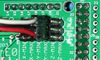
D1, D2 - 二极管


These must be placed in the proper orientation. The band on the diode must be turned the same way as the mark on the board.
Definitely solder D2 in. D2, F1, and F2 are shown installed here.
D1 should only be installed if the 5A rail is powered by 12V. It can be omitted and the Arduino will be powered from USB. You will want D1 installed if you add components to print without a PC. To reiterate, D1 MUST be omitted if you are powering the 5A rail by more than 12V, or the power is not absolutely clean, otherwise you may damage your ramps.
F1 - MFR500 保险丝
This is the smaller yellow fuse. This can be placed in any orientation. When soldering the fuses it is best to use a piece of 3mm filament or something similar to keep the ceramic coating on the pins from blocking proper solder along the through hole.
Since the fuses are the tallest parts, it is simpler and more convenient to solder them last. From this point on, solder the rest of the RAMPS in order of bottom pins, reset switch, terminals, mosfets and then fuses.
F2 - MFR1100 保险丝
This is the larger yellow fuse. This can be placed in any orientation.
Q1, Q2, Q3 - 场效应管

These must be orientated as in the picture. The tall heat sink part of the mosfet needs to be turned the same as the mark on the board.
Mosfet接线端子


This must be oriented where the wire holes are turned towards the edge of the board. Solder a pin on each end and make sure the component is flat on the board and solder the middle pins.
电源接线端子

This can only be oriented in one direction.
底部排针


将排针长端向外焊接到PCB板底部,用于连接Mega2560。可将它们先插到MEGA板上再焊接,注意防止过热损坏Arduino元件。
复位开关

This can only be oriented in one direction.
检查
检查连接是否正确,清理任何悬浮或桥接焊锡。
步进电机驱动板
- 必须插上跳线以设定步进电机微步细分:
 跳线   Yes/No     微步长
 1     2    3
 no   no    no    full step
 yes  no    no    half step
 no   yes   no    1/4 step
 yes  yes   no    1/8 step
 yes  yes   yes   1/16 step
目前默认都是使用1/16微步(三个跳线全部接上)。
- Cut the pin headers to 8 pins long so that they fit each side of the stepper driver.
- Insert the pin headers into the sockets on RAMPS
- Fit the stepper drivers onto the pin headers and solder. Only heat each pin for a few seconds at time to avoid damage to the socket.
光电限位开关
Opto board 2.1 build instructions can be found here on the reprap opto page, and also here for reprapsource.com's instructions.
- Cut the 26awg 3 conductor cable into 3 length.

- Note: you may want until you've built your machine to cut the cables to the perfect length.
- crimp and solder a female connector to the ends of each wire. (solder not necessary with proper crimp tools)
- use the 2.54mm 1x3 housing.
- Connect at least the minimum endstops.
- Cut the 26awg 3 conductor cable into 3 length.


| RAMPS End | |
| SIG (S) | White |
| GND (-) | Black |
| VCC (+) | Red |
| Endstop End | |
| VCC (+) | Red |
| SIG (S) | White |
| GND (-) | Black |
机械限位开关

推荐的固件都会提供配置,实现通过两条线使用机械限位开关。
在板的上部右侧找到"endstops",对每对X, Y或Z轴排针进行如下操作:
- 将RAMPS上的S (top row, labelled to the left)连接到开关的NC端.
- 连接RAMPS上的GND到开关的C端。
Note: The latest firmware such as Marlin seems to use NO as the default pin on the switch. Otherwise you may need to invert the endstops in the firmware. You can use M119 to check your endstops status.
Put the connectors on the motor wires
- solder a female connector to the ends of each wire.
- use the 2.54mm 1x3 housing.
- Shown is the type used for servos in RC projects. See Stepper Motors for info on motors.
热敏电阻连线
Use a 2 pin 0.1" connector to terminate the thermistor wires.
- Connect the cable so the 2 wires go to T0
- Connect the 2 heater wires to D10 (E0H on older boards) and the + connection above it.
- If changing to an unverified firmware it is best to verify heater circuit function with a meter before connecting heater to prevent damage to the extruder.
Pololu carriage

This section assumes you are using Pololu, but there are other options. Insert two 1x8 pin headers into the board. If you bought a kit with one 16 pin header, simply cut it so that you have two 1x8. Make sure that the side with the labels has the long ends of the posts, and the side you want to solder is the side with the heat sink. Doing this backwards will cause you not to see the labels and will most likely not fit. Remember to apply a heat-sink to the largest chip on the back.
最后安装
上机前检查
如果你觉得可能连接有错,仅连接一个步进电机驱动器开始检查。
步进电机驱动器上的电位器实现限流功能。Turn it all the way down (counter clock wise) and back up 25%. Be careful to not force the trimpot, it is delicate. You will need to fine tune the current limit later. Note that it is allways giving the motors that much power, even when not moving, so if your stepper motor drivers are getting hot, you may want to turn it down slightly.
Connect the minimum endstops for X,Y, and Z
连接步进电机 (Do not disconnect or connect motors while powered; if the connection is loose, this will cause the motors to spazz and possibly kill your stepper driver.)
你可能需要这个 代码 在刷固件前检查各个电子器件。
安装固件 (见下面). 刷固件也可在不加载12V电源的情况下进行。
接线
给RAMPS接线很容易。 将挤出头供电线连接到D10, 将热敏电阻的线连接到中部右侧的T0排针,接上步进电机和限位器。从左 到右依次连接步进电机的 红、蓝、绿和黑或红、绿、黄、蓝线到Pololus边上的排针。当你连接限位开关时注意连接标签是否正确(如果你采用3个限位开关,将其连接到MIN (-)插槽)。

注意tesla和tonok固件采用d9,而sprinter和johnny/tonok固件采用d10连接挤出头加热端。
警告
Reversing +/- or otherwise incorrectly connecting power can destroy your electronics and cause fire hazard.
Incorrectly inserting stepper drivers will destroy your electronics and cause a fire risk. Always make sure power and USB is disconnected when removing or adjusting stepper drivers. Always make sure to insert drivers in correct orientation and in the socket correctly.
The endstop pins are Signal - GND - VCC, instead of the VCC - Sig - GND like the rest of RepRaps boards. Make sure to wire them correctly. This is done to allow squeezing fatter traces on the printable board.
Connecting Power
Connect your 12V power supply to the RAMPS shield. Reversing +/- or otherwise incorrectly connecting power can destroy your electronics and cause fire hazard.
The bottom pair of connectors marked 5A power the stepper drivers and Extruder heater/fan (D9, D10). The source should be rated a minimum of 5A.
The pair of connectors above marked 11A power a Heated Bed, or other output (D8). The source should be rated a minimum 11A (if both power rails are connected to the same supply it should have a minimum rating of 16A).
The barrel connector, on the Arduino MEGA, will NOT power RAMPS and will not provide power to the stepper motors, heated bed, etc.
The power connector plug may not be obviously labeled, looking at the power connection the positive is on the left and the negative is on the right of the plug.
供电电源
RAMPS is quite happy with the 12 V line from PCPowerSupply. Or you can hack up a 12V laptop power supply, or other 12 V "wall wart" power supply. Be sure that the power can output 5A or greater. Additional 11A may be needed for heated bed support.
See Connecting power above.
The 3 pins next to the reset switch are meant to optionally connect to your PSU.
The PS_ON pin is intended to switch your power supply on and off. Many firmwares support pulling this pin low with M80 command to turn the power supply on, and M81 to turn it off. This behavior is desired for ATX power supplies and can be modified in firmware to support 5V high power supplies like those borrowed from an Xbox.
Without D1 installed, or when the 12VIN is not connected, the Arduino gets its power from USB. If you want your kit powered without USB connected you need to solder in D1 OR connect VCC to your PSU.
The VCC pin can be connected to your ATX's 5Vsb to continuously power the Arduino from your ATX power supply. You will want to make sure that D1 is not installed or cut out. The Arduino is not designed to be powered directly on the VCC rail and the VIN pin at the same time.
The 5V pin in that connector on RAMPS only supplies the 5V to the auxiliary servo connectors. It is designed so that you can jumper it to the VCC pin and use the Arduino's power supply to supply 5V for extra servos if you are only powered from USB or 5V. Since there is not a lot of extra power from the Arduino's power supply you can connect it directly to your 5V power supply if you have one. You can also leave this pin not connected if you have no plan to add extra servos.
最大输入电压
Power Supply without diode
The 1N4004 diode connects the RAMPS input voltage to the MEGA. If your board does not have this diode soldered in, you can safely input as much as 35V. (The pololus can do up to 35V)
Power Supply with diode
If your board has a 1N4004 diode soldered in, do not apply more than 12 V to it. Original flavor Arduino Mega are rated to 12 V input. While Arduino Mega 2560 can take 20 V, it is not recommended.
Firmware and Pin Assignments
RAMPS 1.4 uses the same pin definitions as 1.3.
You will need the Arduino software at http://www.arduino.cc/en/Main/Software to upload the firmware to Arduino Mega. Arduino MEGA 2560 Rev3 requires Arduino software version 0023.
Sprinter and Marlin are popular and stable firmwares for RAMPS as of 3/28/2012. Pronterface is a cross platform printer control program that can be used for testing/printing.
Working preconfigured sprinter firmware can be downloaded at http://ultimachine.com/sites/default/files/UltiMachineRAMPS1-4Sprinter.zip . Mechanical is in the folder ending with ME, optical endstop firmware is in the folder ending in OE.
Others (Need pins set in Firmware as below):
- mechanical endstops (now the default ultimachine.com option) require #define OPTO_PULLUPS_INTERNAL 1 to be added to configuration.h if not there by default.
Here are the pin definitions for this board.
// For RAMPS 1.4
#define X_STEP_PIN         54
#define X_DIR_PIN          55
#define X_ENABLE_PIN       38
#define X_MIN_PIN           3
#define X_MAX_PIN           2

#define Y_STEP_PIN         60
#define Y_DIR_PIN          61
#define Y_ENABLE_PIN       56
#define Y_MIN_PIN          14
#define Y_MAX_PIN          15

#define Z_STEP_PIN         46
#define Z_DIR_PIN          48
#define Z_ENABLE_PIN       62
#define Z_MIN_PIN          18
#define Z_MAX_PIN          19

#define E_STEP_PIN         26
#define E_DIR_PIN          28
#define E_ENABLE_PIN       24

#define SDPOWER            -1
#define SDSS               53
#define LED_PIN            13

#define FAN_PIN            9

#define PS_ON_PIN          12
#define KILL_PIN           -1

#define HEATER_0_PIN       10
#define HEATER_1_PIN       8
#define TEMP_0_PIN          13   // ANALOG NUMBERING
#define TEMP_1_PIN          14   // ANALOG NUMBERING
源文件
| FILE ID# | TYPE | DESCRIPTION | DOWNLOAD |
|---|---|---|---|
| File:ArduinoMegaPololuShield.zip | Eagle Files | These are the files you need to make the board.(Use the File: link to the left to access older versions of the file.) | media:ArduinoMegaPololuShield.zip |
| File:RepRapjr.lbr | Eagle Libraries | The components used in this board are here. see Eagle_Library | media:RepRapjr.lbr |
Bill of Materials
| ID | Description | Quantity | Part Number | Reichelt Order Number | Digikey Part Number (Description) |
|---|---|---|---|---|---|
| U1 | Arduino Mega | 1 | 2560 or 1280 | N/A | |
| U2,U3,U4,U5 | Pololu stepper driver boards | 4 | A fifth one can be used for a 2nd extruder or extra axis | N/A | |
| C2 | 100nF capacitor (0805)(> highest planned voltage) | 1 | |||
| C1,C5,C8 | 10uF capacitor (153CLV-0405)(>5V) | 3 | |||
| C3,C4,C6,C7,C9,C10 | 100uF capacitor (153CLV-0605)(> highest planned voltage) | 6 | |||
| R1,R7,R11,R21,R22 | 4.7K resistor (0805)(1%) | 5 | |||
| R2,R3,R4,R5,R6,R8,R9,R10 | 100K resistor (0805) | 8 | |||
| R12 | 1K resistor (0805) | 1 | |||
| R23,R24,R26 | 1.8K resistor (0805) | 3 | |||
| R16,R17,R18,R19,R20 | 10K resistor (0805) | 5 | |||
| R13,R14,R15 | 10 ohm resistor (0805) | 3 | |||
| Q1,Q2,Q3 | N-channel Mosfet | 3 | STP55NF06L | ZXM 64N035 L3 | 497-6742-5-ND (MOSFET N-CH 60V 55A TO-220) |
| D1,D2 | Diode | 2 | 1N4004 | 1N 4004 | 1N4004FSCT-ND (DIODE GEN PURPOSE 400V 1A DO41) |
| F1 | PTC resettable fuse (30V, Hold5A, Trip10A) | 1 | MF-R500 | PFRA 500 | MF-R500-ND (FUSE PTC RESETTABLE 5A HOLD) |
| F2 | PTC resettable fuse (Hold11A) | 1 | MF-R1100 | RGEF1100-ND (POLYSWITCH RGE SERIES 11.0A HOLD) | |
| J2 | D8-D10 Outputs // 6 position screw terminal (min 11A per contact) OR Jack/Plug connector pair | 1 | 282837-6 | AKL 101-06 | WM7857-ND (CONN TERMINAL BLOCK 6POS 5.08MM) Alternative: 1x 609-4284-ND & 1x 609-4218-ND. May prevent overtemp events |
| LED1 | Green LED (0805) | 1 | |||
| LED2,LED3,LED4 | Red LED (0805) | 3 | |||
| S1 | Push button switch | 1 | B3F-3100 | TASTER 3305B (should fit footprint also, but button will overhang board edge) | 450-1648-ND (SWITCH TACT RA H=6.35MM) |
| X1 | Power jack (Plug and fixed receptacle)(Min 11A per position more is better) | 1 | MSTBA 2,5 and MSTBT 2,5 (5.04mm spacing 4 connector) | WM7847-ND (CONN HEADER 4POS 5.08MM R/A TIN) & WM7953-ND (CONN TERM BLOCK 4POS 5.08MM R/A) | |
| 2 x 3 pin header | 8 | 961206-6404-AR | 3M9459-ND (CONN HEADER VERT DUAL 6POS GOLD) | ||
| 4 pin header | 5 | 961104-6404-AR | SL 1X36G 2,54 (3 of these) | 3M9449-ND (CONN HEADER VERT SGL 4POS GOLD) | |
| 6 pin header | 2 (? - from http://gala-automation.com/index.php/component/content/article/26-reprap-tutorials/42-ramps-14-bom) | 961106-6404-AR | 3M9451-ND (CONN HEADER VERT SGL 6POS GOLD) | ||
| 2 x 18 Pin Stackable Female Header (non stackables can be used with plated through holes) | 1 | MALE: SL 2X25G 2,54 (2 of them, shortened with a saw or pliers) | S7121-ND (CONN HEADER FMAL 36PS.1" DL GOLD) - Not Stackable | ||
| 8 Pin Stackable Female Header (non stackables can be used with plated through holes) | 5 | S7041-ND (CONN HEADER FEMALE 8POS .1" GOLD) - Not Stackable | |||
| 6 Pin Stackable Female Header (non stackables can be used with plated through holes) | 1 | S7039-ND (CONN HEADER FEMALE 6POS .1" GOLD) - Not Stackable | |||
| 24 Pin Female Header * Note * | 2 | Required to carry enough current for motors | S7057-ND (CONN HEADER FMALE 24POS .1" GOLD) - Rated @ 3A / Pin | ||
| 8 Pin Female Header * Note * | 4 | Required to carry enough current for motors | S7041-ND (CONN HEADER FEMALE 8POS .1" GOLD) - Rated @ 3A / Pin | ||
| 0.1" Jumpers | 15 | A26242-ND (SHUNT LP W/HANDLE 2 POS 30AU) | |||
| Circuit Board | 1 | v1.4 | N/A |
Note * You can use Female Headers which are not the exact size, but they are hard to break/cut so in this case buy some extra! (one wasted header per cut)
A BOM for sourcing the RAMPS components from Mouser is also available in this google spreadsheet
Shopping lists for v1.4 [1] .