RAMPS 1.4/zh tw
Contents
- 1 摘要
- 2 安全提示
- 3 組裝
- 3.1 焊接RAMPS擴展板
- 3.1.1 C2 - 100nF電容
- 3.1.2 LED1 - 綠色提示燈
- 3.1.3 LED2, LED3, LED4 - 紅色提示燈
- 3.1.4 R13, R14, R15 - 10 Ohm電阻
- 3.1.5 R12 - 1K電阻
- 3.1.6 R23, R24, R25 - 1.8K電阻
- 3.1.7 R1, R7, R11, R21, R22 - 4.7K電阻
- 3.1.8 R16, R17, R18, R19, R20 - 10K電阻
- 3.1.9 R2, R3, R4, R5, R6, R8, R9, R10 - 100K電阻
- 3.1.10 C1, C5, C8 - 10uF電容
- 3.1.11 C3, C4, C6, C7, C9, C10 - 100uF電容
- 3.1.12 錫爐迴焊
- 3.1.13 排針
- 3.1.14 驅動板插座
- 3.1.15 D1, D2 - 二極管
- 3.1.16 F1 - MFR500 保險絲
- 3.1.17 F2 - MFR1100 保險絲
- 3.1.18 Q1, Q2, Q3 - MOSFET場效電晶體
- 3.1.19 MOSFET 壓接端子
- 3.1.20 電源壓接端子
- 3.1.21 底部排插(連接Mega2560使用)
- 3.1.22 復位開關
- 3.1.23 焊點檢查
- 3.2 步進馬達驅動板
- 3.3 光電限位開關
- 3.4 機械限位開關
- 3.5 Put the connectors on the motor wires
- 3.6 熱敏電阻連線
- 3.7 Pololu carriage
- 3.1 焊接RAMPS擴展板
摘要
相較於1.3版,RAMPS 1.4將前代的電阻電容元件更換為SMD,以適用更多被動元件。雖然這會使組裝時增加一些步驟,但我們使用的零件屬貼片零件中較大的一類,所以還是一樣容易組裝。


安全提示
![]()
就算你接上的電源是僅有12V的電源,但還是請預先做好基本保護措施,以避免火災發生。 檢查工作室內備有煙霧探測器,沒有嗎?快去買個先!
組裝
準備工具: 烙鐵,焊錫,鑷子 吸錫線、吸錫器、助焊劑
亦可使用: 焊膏搭配電熱板或電熱爐
焊接RAMPS擴展板

焊接RAMPS 1.4包括貼片焊接和通孔焊接兩部分。
焊接貼片元件有幾種方法。板上所有的SMT元件都有兩個焊盤,所以把元件兩個引腳依次焊上很容易。先在一個焊盤上抹點焊錫,有助焊劑的話,就在附錫的焊盤上抹點兒。對準引腳與焊盤,用鑷子固定住元件,加熱焊錫使之粘附(保證加熱均勻,以防造成冷焊),然後再焊另一個引腳。也可以使用錫爐迴焊法(HotplateReflowTechnique)。
先焊接貼片元件,然後是板上的PTH,最後焊接板下面的引腳頭。
C2 - 100nF電容

放置時不區分方向。
LED1 - 綠色提示燈

將綠色LED上的綠線(或綠點)置於+號反向,焊上它。
LED2, LED3, LED4 - 紅色提示燈

將紅色LED上的綠線(或綠點)置於+號反向,焊上它。
※注意!就算LED是紅色的,他的負端還是用綠色的點或線標示。
R13, R14, R15 - 10 Ohm電阻

放置時不區分方向。
R12 - 1K電阻

放置時不區分方向。
R23, R24, R25 - 1.8K電阻

這裡該使用1.8K電阻,圖上我們是使用1K代替,使電路能承受較高的電壓。
電阻元件沒有極性,不用分辨方向即可焊接。
R1, R7, R11, R21, R22 - 4.7K電阻

電阻元件沒有極性,不用分辨方向即可焊接。
R16, R17, R18, R19, R20 - 10K電阻

電阻元件沒有極性,不用分辨方向即可焊接。
R2, R3, R4, R5, R6, R8, R9, R10 - 100K電阻

電阻元件沒有極性,不用分辨方向即可焊接。
C1, C5, C8 - 10uF電容

這類電容有正負極之分,故必須放置在正確的方向。電容蓋帽上印有黑色切圓的為負極,請將此電容底座對準電路板線匡後焊上
C3, C4, C6, C7, C9, C10 - 100uF電容

注意電容量標示為100uF與前步驟不同,其他與前步驟相同,辨認正負極再予放置於電路板上正確位置。
錫爐迴焊


如果你使用錫爐迴焊法進行焊接,那請在此時開爐迴焊;如果你使用的是電烙鐵,那你應該已經焊完前述零件了。
因為此步驟後難以回頭修改或檢查電路,所以請務必於焊接完後確認SMT已焊上電路板上。
排針

依照片位置對準排針腳進行焊接。焊接時先焊上一腳先求固定,檢查有無間隙,若未完全與電路板貼合請用烙鐵補加熱一次使之貼合。 ※新手請注意,焊接排針時,熱會迅速由銅針導至另一端,所以請勿於焊接時直接以皮膚接觸,否則會被燙傷。
如果您要使用額外的排針引腳,現在是時候可以焊上了。
驅動板插座

將驅動板母座放置於如圖中的正確位置,此外你也可以使用1x8及1x6 pin排插母座佈置成垂直排列狀,確認擺放位置後焊上這些排針母座。
D1, D2 - 二極管


These must be placed in the proper orientation. The band on the diode must be turned the same way as the mark on the board.
Definitely solder D2 in. D2, F1, and F2 are shown installed here.
D1 should only be installed if the 5A rail is powered by 12V. It can be omitted and the Arduino will be powered from USB. You will want D1 installed if you add components to print without a PC. To reiterate, D1 MUST be omitted if you are powering the 5A rail by more than 12V, or the power is not absolutely clean, otherwise you may damage your ramps.
F1 - MFR500 保險絲
This is the smaller yellow fuse. This can be placed in any orientation. When soldering the fuses it is best to use a piece of 3mm filament or something similar to keep the ceramic coating on the pins from blocking proper solder along the through hole.
Since the fuses are the tallest parts, it is simpler and more convenient to solder them last. From this point on, solder the rest of the RAMPS in order of bottom pins, reset switch, terminals, mosfets and then fuses.
F2 - MFR1100 保險絲
This is the larger yellow fuse. This can be placed in any orientation.
Q1, Q2, Q3 - MOSFET場效電晶體

MOSFET電晶體有極性,請依照照片方向焊接,如果你有要為MOSFET加上散熱片,板上標示安裝。
MOSFET 壓接端子


壓接端必須朝向電路板外緣焊接上,並確保塑膠座已平貼於電路板上,與排針焊接技巧相同。
電源壓接端子

請將壓接端開口朝電路板外緣擺放再行焊接。
底部排插(連接Mega2560使用)


排針焊接方法與前述原則相同,此處可以先將排針插在Mega2560上以之支撐,方便焊接,但請注意別加熱時間太久,否則可能會損壞Arduino板上的零件。
復位開關

確認正負極再行焊接。
焊點檢查
檢查之前所有步驟焊接是否確實。
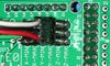
步進馬達驅動板
使用斜口鉗裁取8pin
- 必須插上跳線設定微步進數:
 跳線有無(yes有/No無)    微步設定
 1       2       3
 no      no      no    full  步
 yes     no      no    half  步
 no      yes     no    1/4   步
 yes     yes     no    1/8   步
 yes     yes     yes   1/16  步
目前預設都是使用1/16步,也就是三個跳線都裝上的狀態。
- Cut the pin headers to 8 pins long so that they fit each side of the stepper driver.
- Insert the pin headers into the sockets on RAMPS
- Fit the stepper drivers onto the pin headers and solder. Only heat each pin for a few seconds at time to avoid damage to the socket.
光電限位開關
Opto board 2.1 build instructions can be found here on the reprap opto page, and also here for reprapsource.com's instructions.
- Cut the 26awg 3 conductor cable into 3 length.

- Note: you may want until you've built your machine to cut the cables to the perfect length.
- crimp and solder a female connector to the ends of each wire. (solder not necessary with proper crimp tools)
- use the 2.54mm 1x3 housing.
- Connect at least the minimum endstops.
- Cut the 26awg 3 conductor cable into 3 length.


| RAMPS End | |
| SIG (S) | White |
| GND (-) | Black |
| VCC (+) | Red |
| Endstop End | |
| VCC (+) | Red |
| SIG (S) | White |
| GND (-) | Black |
機械限位開關

The recommended firmware will provide a configuration to use mechanical endstops with just two wires.
Find the area labelled "endstops" in the upper right corner of the board and for each of the X, Y, and Z pairs of pins (label should be below each set) do the following:
- Connect S (top row, labelled to the left) on RAMPS to NC on the switch.
- Connect GND on RAMPS to C on the switch.
Note: The latest firmware such as Marlin seems to use NO as the default pin on the switch. Otherwise you may need to invert the endstops in the firmware. You can use M119 to check your endstops status.
Put the connectors on the motor wires
- solder a female connector to the ends of each wire.
- use the 2.54mm 1x3 housing.
- Shown is the type used for servos in RC projects. See Stepper Motors for info on motors.
熱敏電阻連線
Use a 2 pin 0.1" connector to terminate the thermistor wires.
- Connect the cable so the 2 wires go to T0
- Connect the 2 heater wires to D10 (E0H on older boards) and the + connection above it.
- If changing to an unverified firmware it is best to verify heater circuit function with a meter before connecting heater to prevent damage to the extruder.
Pololu carriage

This section assumes you are using Pololu, but there are other options. Insert two 1x8 pin headers into the board. If you bought a kit with one 16 pin header, simply cut it so that you have two 1x8. Make sure that the side with the labels has the long ends of the posts, and the side you want to solder is the side with the heat sink. Doing this backwards will cause you not to see the labels and will most likely not fit. Remember to apply a heat-sink to the largest chip on the back.