AssemblingDarwinMachinery
Contents
- 1 Cartesian Assembly (Mechanical)
- 1.1 Notes to editors:
- 1.2 Mechancial description
- 1.3 Preparation
- 1.4 Mechanical Assembly
- 1.4.1 X Axis
- 1.4.2 XY frames
- 1.4.3 Studding idlers
- 1.4.4 Studding drive
- 1.4.5 Installing the Z posts
- 1.4.6 Installing the idlers
- 1.4.7 Assembling the bed constraints
- 1.4.8 Fitting the Bed
- 1.4.9 Mounting the top XY frame
- 1.4.10 Attaching the base diagonals
- 1.4.11 Setting the z idler ties
- 1.4.12 Z belt
- 1.4.13 Assembling the Y axis
- 1.4.14 Side diagonals
- 1.4.15 Installing the extruder and fan
- 1.4.16 Squaring up
- 1.5 Z Axis trouble shooting
Cartesian Assembly (Mechanical)
Hello, and welcome to the first Cartesian assembly page! Here we will assemble the mechanical parts of Darwin's Cartesian robot step by step. Before putting it together you will need to read through the preparation section and make sure you've got everything you need, and then mod some standard parts to fit the design. When that's done, you'll be ready to go for the assembly.
Should you have any problems, please check the Cartesian Assembly FAQ.
Good luck!!
Notes to editors:
Ello! If you're reading this, you've probably got some of the bits and it's all very exciting! When you put it together, it'd be great to have your feedback to strengthen the design and make RepRap the best it can be...
Feedback
Design Faults page: If you discover any serious design faults specific to part designs which prevent you from making Darwin work, please list them here. These will be remedied, if at all possible, before the release.
Concept improvements: If you spot any things which are particularly awkward, have any ideas on a more efficient approach, or see any wasted opportunity please list your comments here. These notes will be a very useful resource to design of the second release.
Editing
Cartesian Assembly FAQ: if there's anything which needs explaining outside this page, please use this resource. I'll be checking email more frequently than this so please don't hesitate to drop me a line if I haven't explained something properly!
BOM: parts references will always refer to this. Please don't be tempted to include mini parts lists duplicated at the top of each subassembly section on this page just yet, or get too specific with references in the text. Whilst this would makes it more readable, centralising the list makes it much simpler to mod. There's a lot of parts on the BOM, so I've probably missed a few things out by mistake. During assembly, if you'd like to gather your bits using the BOM before assembling, omitted parts will quickly become obvious. Finding these omissions is a valuable thing, so if you'd like to update the BOM and note changes made in the edit notes at the bottom that would be fantastic.
Cheers again!
Mechancial description
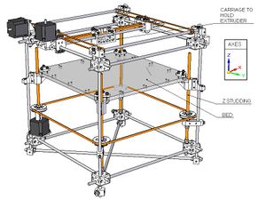
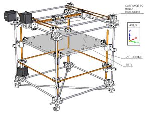
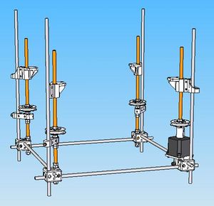
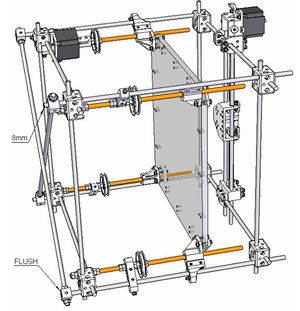
The Z axis is the vertical component. It moves the bed up and down. Unlike the X and Y axes, the Z axis is used less frequently as it is only active when a layer is finished (it moves the bed down a notch). Thus it can move more slowly that the X and Y axes, and is driven via 4 screw threads synchronised by a timing belt. This gives slow speed but increased precision.
The Y axis is used in combination with the X axis to move the print head horizontally over the bed. Because they are in constant use they need to move quickly and are therefore belt driven.
Once set up, these axes find their home positions using opto-switches. From the home positions the axes can achieve repeatable movements to within 0.1 mm.
Preparation
Space
You'll need a good bit of bench space, something in the region of 1 m x 2 m should be fine. At least half a meter square of this space should be flat for setting up frames. Pots to keep different bits in are a big help.
Time
Preparation, assembly and wiring should each take about a day, so find a stereo and get some biscuits in!
Bill of Materials (BOM)
The BOM is on a separate page to reduce the amount of scrolling you need to do (Alt + Tab will quickly switch windows for you). It covers both mechanical and electrical sub-assemblies.
Tools
In addition to the BOM, you will need the following tools for preparation and assembly:
- Hacksaw
- Drill (+ bits Ø7mm & Ø5.4 or 6mm)
- File
- Vice
- G-clamp
- Scalpel
- Scissors
- Spanner for M8 nut (2 off)
- Spanner for M5 nut
- Allen key for M5 cap bolt
- Allen key for M5 grub
- Superglue
- Permanent marker
- Rag or tissues to wipe grease
- Kettle
- Parcel Tape, Clear
- Hole punch, for paper (optional)
Components
RP parts
You will need to receive these parts before you can start. A glossary of RP parts is included with the BOM so you know what the parts actually look like.
Part Equivalents
Since not everyone has a rapid prototyping machine, but are still interested in constructing a Darwin machine, we have created a page that lists each part, and equivalent parts you can construct yourself.
Standard parts
You will need to buy in all the parts on the BOM marked as 'fasteners', 'Ø8 rods/studding' and 'others'.
To generate shopping lists, copy and paste the BOM into a spreadsheet program. You can then sort by category. Whilst this requires a bit of processing, I believe this is much better than creating duplicate lists which would make updating a real nightmare. Zach's currently working his magic with SQL to solve the problem, but for now, please bear with this central list.
For 'others': the part number has been included from either RS or Farnell (the R or F prefixing each part number simply denotes which company the part comes from, so delete this prefix when you enter the number into their search engine). Visit http://rswww.com/ or http://uk.farnell.com/ for the relevant part details.
For 'fasteners' (nuts and bolts): it's worth getting an extra percentage of extra of each type in case you loose any. For your bolt and grubs, if possible, get the gnarly faced variety. Standard flat faces will certianly do, but they have less of bite into the rods they'll be clamping into. Your local fasteners stores will have much if not all of what you are looking for, including studding: email or fax in a request for a quotation to check availability and pricing.
For 'Ø8mm rods and M8 studding': buy in stock lengths of 1-1.5 m. There is a section on cutting to size later. Bear in mind when you make your order you can usually cut two or more parts out of one length of stock. If the expense of stainless puts you off, mild steel will do fine - but it does need to be lightly oiled - worth keeping it in mind if your machine's going to sit in the lounge. Farnell stock codes: 7092209 (SS rod) 8858691 (studding). Steel rod and stud may be less expensive at your local hardware store, although they may not have sufficient quantities on hand for your needs. It is quite likely you have a local steel supplier who sells metric/imperial steel rod and studding (along with girders, roofing, etc.), and they will be less expensive than anyone else. (You may find it convenient to bring a pair of bolt cutters in this case, if you need to fit 10 ft lengths of steel studding into a small car.)
Cutting steel rods
You will need to cut the Ø 8mm rods and studding to the lengths specified in the BOM. Cut the steel rods to the appropriate lengths using a hacksaw and vice.
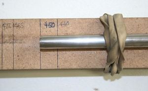
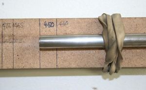
Cutting these lengths is a fairly long job, so making a measurement jig will save you a lot of time: I used a strip of scrap MDF, marked off the lengths I needed from a datum end and made a round impression along the length of the wood by over-clamping it in the vice against a full length of rod. This impression made the rod easier to sit with the jig.
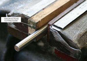
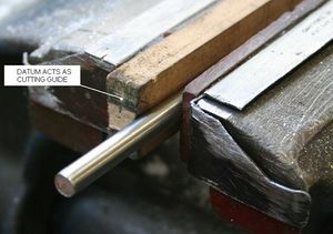
To cut the rod, I clamped it against the jig with one end at the length marker, the other hanging over the datum end. A rubber band was used as a third hand. The datum end of the jig is useful to ensure a perpendicular cut at the right length.
You should be able to get lengths to within ± 0.5 mm.
De-burr all edges using a file and vice. For studding lengths, make sure nuts can be easily wound onto the studding.
Also make sure you clean your rods thoroughly. Apart from looking better, some of them will be used as bearing surfaces.
Making the Bed
You will need to buy nice sheet of MDF for this, 12mm thick, 400 mm square. If you can get your supplier to cut it to that, you're onto a winner. If not, make sure you wear a mask when you cut it - the particle sizes are carcinogenic if inhaled. Lovely.
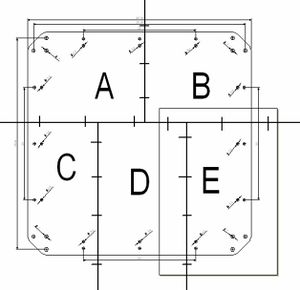
Print the Paper Bed Templates
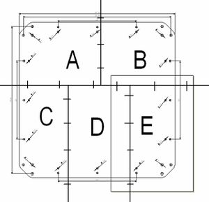
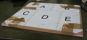
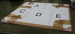
Download the PDF templates in the zip file at the bottom of this page. Print out on A4 at a scale of 1:1 (make really sure your software isn't set to any kind of fit in the page scaling settings) and tape them together so that, after a bit of cutting, all the lines match up to complete the above image. Use the hole-punch or a hobby knife to cut out small holes along the alignment lines and at the intersections of alignment lines in order to better align the sheets. The dimensions are for reference purely so that you can check you've got your template right. You should aim to have made the template to within ±1mm. (The bed is symmetrical).
Download one of the following PDF templates:
File:BedtemplatesheetsA2.pdf
File:BedtemplateImperialLetterPrint.zip
File:BedtemplateA4printing.zip
File:Bedtemplate.dxf : Or use this CAD file to generate your template.
I found it was possible to tape the template to the board with parcel tape. I preferred this over glue because it was possible to remove the template afterwards. However, it is a more risky option because the template might shift in mid drill (if you do glue, just make sure that, when you install the bed, the paper side goes on the bottom).
Now shave the corners and drill the holes out. Note that:
- the board should be 1mm wider than the template on all sides
- the corner holes are all Ø 7 mm
- the side holes are all Ø 5.4 mm (a 6 mm will do if you don't have the bit)
When done, remove the template and peel off the scrags of MDF around the holes on the underside of the board.
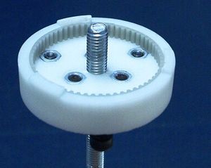
Toothed pulley moulding
To make the toothed pulleys we will need to mould some Polycaprolactone (capa) into the toothed belt (a nod to Vik here for such a genius idea) using some !RP moulds.
To find all the parts you need for this section, check out the BOM for the Cartesian robot.
You will be dealing with boiling water so take care and use gloves where appropriate.
Z toothed pulleys
To find all the parts you need for this section, check out the BOM for the Cartesian robot.
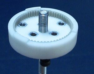
Load the female mould with M5 nuts and bolts (for ejection) and belt. Wind the ejector bolts so the ends are flush with the bottom of the mould. Make sure the belt is flat against the side and meets itself neatly:
Wind two M8 nuts and washer onto the studding and drop the female mould onto the studding as shown. Twist the two nuts against each other to lock onto the studding.
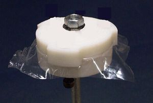
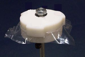
Now cut a circle out of the plastic bag. The diameter should be just smaller than that of the teeth. This plastic disc will be used to line the bottom of the mould, making release possible. Cut a small X in the centre so that the studding can poke through, and place the liner on the bottom of the mould. The liner should lie flat.
Prepare another liner for the male side. This should have an X cut into the centre, but this time the diameter should exceed the limits of the mould. Alternatively, just line the mould with a single layer of PVC food wrap; this can go under the section of belt and if you leave extra you can fold it over the top of the capa you're about to load in.
Heat up some capa and mould it in your hands to approximately the right shape. Re-heat the capa.
The next stage all happens very quickly:
- Put the capa into the mould.
- Thumb the capa into the teeth and around the studding.
- Push the male release liner over the studding and onto the capa.
- Push the male down on top of the capa, lining up the 3 stubs with the female's stubs.
- Slide a washer on and wind down an M8 nut.
- Using spanners, tighten the mould until the male and female stubs meet, squashing the capa into shape. Excess might squeeze out of the mould. You can cut this off later.
- Leave for 30 seconds.
Release the mould pressure and unscrew the studding - take it out of the assembly completely. Don't forget to do this before you touch the ejector pins!!
Pull off the male half. Cut off any excess with scissors or side cutters, and crank up the ejector pins to prize the job out of the mould.
You will probably have to repeat this process until the gear is fully formed.
Clean the open side of the teeth by cutting them at 45°. Don't cut the top rim off, but by all means tidy it up.
Pull some belt over the pulley. If the belt rolls easily over the tooth made at the belt join without causing a skip, you got lucky. For the rest of us, have a closer look at this tooth. It might just have a bit of flashing on it which cases the skip, in which case snip the flashing off. The likely problem is, however, that the joint tooth is too wide. On the next press, you will need to put a strip of paper or masking tape (which is more inclined to stay put) behind the belt to reduce its circumference slightly.
You may need to do this several times before you get it right. Persevere.
You need 4 Z pulleys ;-) Don't worry, the rest are much easier.
Y toothed pulleys
To find all the parts you need for this section, check out the BOM for the Cartesian robot.
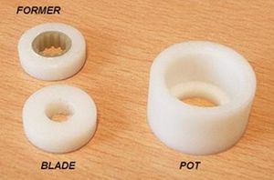
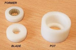
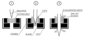
Load the former with belt. Make sure the belt is flat against the side and meets itself neatly.
Put the blade into the pot, then the former.
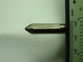
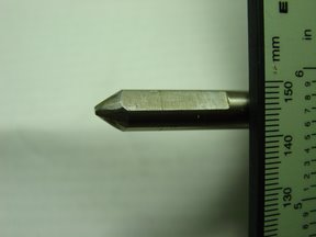
File a spike onto the end of the 8 mm rod (profile similar to diagram below). The spike length should be between 20 and 30 mm long. Now here's something for the American courts: You have just made a spike. Take care not to stab yourself.
Now file a flat up the length of the spike to fit the Y blade profile like this:
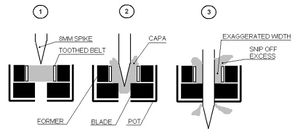
http://picasaweb.google.co.uk/VikOlliver/RepRap02/photo#5083640578583151106Heat up a nugget of capa. Hand mould it into a plug approximately the volume of the belt former hole and then reheat. Also heat up the spike in a separate vessel. Warning: You now have a HOT SPIKE!! Use gloves etc.
Load the belt former with capa and poke the spike through as shown. Make sure the flat on the spike is aligned with the flat on the Y blade as you push it through.
Fold over the excess at the top of the mould while it is still warm to form a small rim over the side of the belt. This will be useful later to stop the belt from falling off the teeth when it's in use.
Allow to cool.
You will need 2 Y pulleys. Store these somewhere safe.
X toothed pulleys
To find all the parts you need for this section, check out the BOM for the Cartesian robot.
This is very similar to the above.
Mould assembly is the same, but switch the Y blade for the X blade.
File a flat onto the length of the major shaft of the motor to fit the X blade profile.
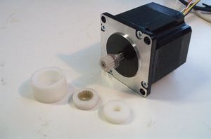
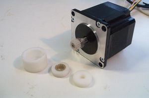
Now, similar to the procedure used for the Y pulley, put a capa plug into the belt collar. Instead of using the spike to make the hole, work a small through-hole into the capa plug with a small screwdriver, just big enough to fit the motor shaft. Now put the motor shaft into the capa, through the blade and allow to set. Remove the motor.
Cut off any entrails at the bottom and pull the mould apart.
Trim excess and test.
Put a washer on the motor shaft, then superglue the pulley onto the motor, with the teeth starting 2 mm from the end of the shaft.
You don't need any more toothed pulleys!
Mechanical Assembly
Prepared? ;-)
General Notes:
- Always include washers with nuts and bolts where possible. It prevents damage to the parts, and reduces the chance of the nut coming loose. They generally won't be mentioned in the instructions, so you need to be on the ball with the washers.
- If you see a picture, don't try to build it straight away - there's usually a careful order which the text will reveal.
- Pay attention to the position and orientation of parts in the pictures. The module designs are often deliberately symmetrical which means there'll be lots of inviting holes you really don't want to go down...
- "Caps" refer to bolts with cylindrical allen key heads (cap screws). You can get away with anything that doesn't taper, but caps look good.
- Do the sections in the order they come.
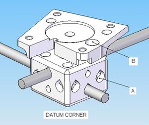
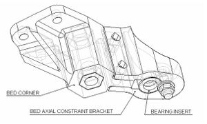
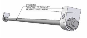
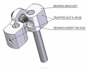
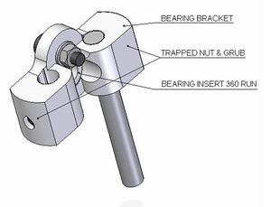
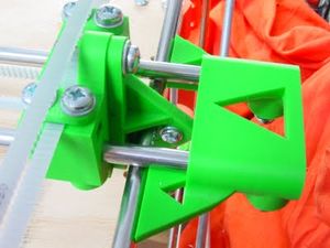
- For Darwin, the steel rods are always locked to the !RP components with trapped nuts, displayed here in this sectioned corner bracket. As the grub or bolt is tightened, the rod is pushed into the !RP housing creating a simple friction fit.
The nut must always be put in place before the rod. The insertion can sometimes be fiddly, but with a bit of practice becomes second nature. By the end of this you'll be an allen-key samurai, and levitating nuts with your hexagonal magic wands.
For the corner bracket, entry holes for the nuts are marked in the diagram. However, for the rest of the parts the nut is usually pushed down the same barrel which the rod will sit in. Grooves down the length of the barrel are usually included to allow the nut to slide down with a bit of force from the large allen key. Place the small allen key in the tightening hole to catch it and wiggle it into the hexagonal counter sink.
Get the rod in to stop the nut falling out, and finish by inserting the grub or bolt via the tightening hole, and tighten (sometimes you will find it easier the preassemble the nut and grub screws before insertion, sometimes not). In many cases (particularly for the eight corner blocks) a nut and its associated grub screw can be pushed in through a hole opposite where they will end up; to do this screw in the grub screw by just one turn, screw a long cap screw into the other side of the nut (so the nut is between the grub screw and the cap screw holding them together); then you can use the cap screw as a handle to insert the nut and grub screw; simply unscrew the cap screw when they are located.
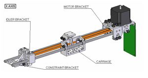
X Axis
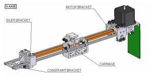
First we'll make the x-axis sub-assembly. A list of all the parts you need for this section can be found in the BOM for the Cartesian robot.
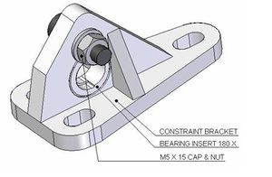
Idler and constraint bracket
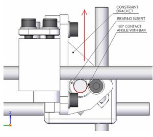
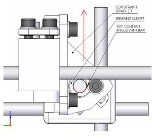
Push the 'Bearing insert 180 X' into the constraint bracket and secure with an M5 x 15 cap and nut (washers essential):
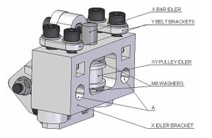
Loosely bolt this onto the back of the idler bracket with some M5 x 15 caps.
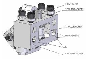
Place the XY pulley idler into the cavity with a lightly greased M8 washer either side. Put the lightly greased idler rod down through the vertical hole, through the idler and washers and into the push fit hole at the bottom.
Load M5 nuts into the square holes either side of the idler cavity and loosely fit the y belt brackets with M5 x 15 caps.
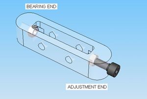
Load two trapped nuts via A (in the diagram), wiggle into their cavities and add grubs.
Carriage
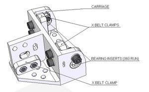
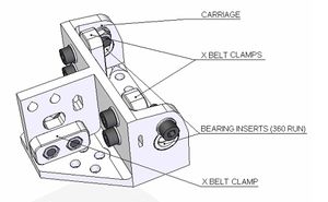
Push in the bearing inserts (360 run) and lock in place with M5 x 15 caps.
Load the three belt clamps with trapped nuts and secure with M5 x 15 caps. The rear belt clamp can slide up and down - it will act as an adjustable bearing on the X rod.
Motor bracket
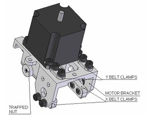
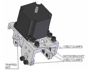
Put the X motor (complete with toothed pulley) on the bracket, wires trailing back and left with respect to this picture. Fasten with M5 x 15 caps. You will probably find that you can't get washers onto the back of the motor's flange plate, but use them on the nuts.
Loosely fasten the 2 Y belt clamps with M5 x 15 caps.
Loosely fasten the 2 X belt clamps with M5 x 15 caps. These will act as bearing surfaces on the XY frame. Leave them loose for now.
Insert 2 trapped nuts and grubs down the barrels of the motor bracket. Load the X rods down the barrels of the motor bracket to prevent the trapped nuts from spilling out.
X axis assembly
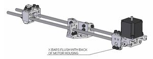
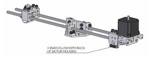
Push the X rods (2 of 'Rod 520') flush with the back of the bracket. Lock them in by tightening the trapped nuts in the barrels.
Slide on the carriage and the idler:
Don't tighten anything else just yet, and put the assembly to one side.
XY frames
A list of all the parts you need for this section can be found in the BOM for the Cartesian robot. To assist assembly you will also need:
- 1 diagonal tie bracket with inserted M5 nut & M5 x 15 cap bolt
- 4 of the shortest lengths of Ø8 mm rod on the list
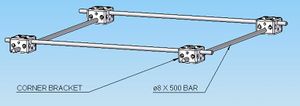
First we will make the bottom XY frame:
Note the different heights of the rods.
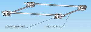
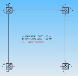
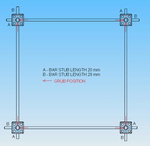
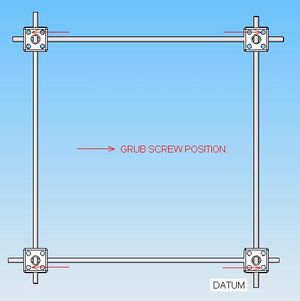
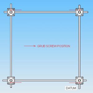
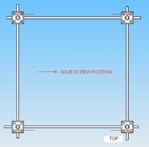
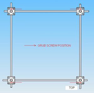
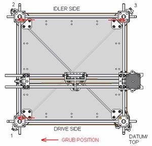
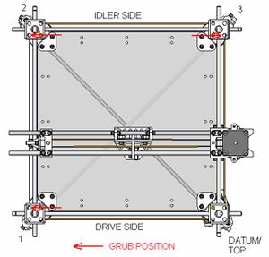
Get the assembly loosely together (teardrop orientation on the brackets doesn't matter, and the stub lengths will be dealt with in the next step), complete with trapped nuts and grub screws always on the side facing inwards, as indicated with red arrows below:
Note also that rod stubs protrude after the corner blocks. These will serve as anchor points for the diagonal ties.
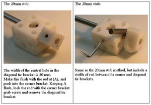
The lengths of the stubs is best determined by the following rules:
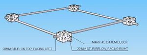
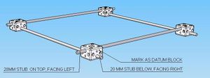
- for each rod, one stub must be 20mm, the other end 28mm
- no two stubs of the same length are allowed on one corner
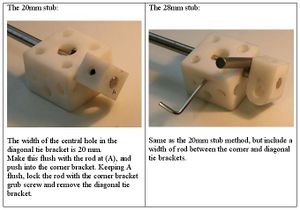
Good luck, and here's how best to use spacers to the make sure the stub lengths are correct.
You should be able to complete the XY frame.
Check:
- Stubs are correct lengths
- All grubs are tight
If that's all good, give the grubs a final tighten, and put a bit of welly into it.
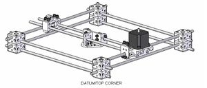
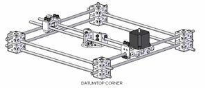
We need to make one of these corners a datum for the rest of Darwin. Pick out the corner shown below and pull it towards you. If the stub lengths are the reverse of the diagram below, just flip the frame over. Mark this block with permanent marker "DATUM" (on the top surface so you know which way is up).
Now to make the top XY frame:
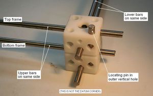
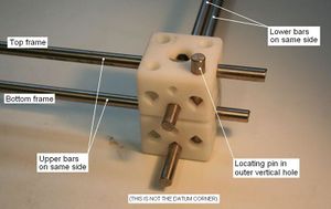
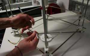
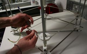
Loosely assemble the parts the same as you did for the lower frame. Now lift the top frame and put it on top of the bottom frame. Position it such that the higher rods for each frame sit on the same side, same for the lower rods. Locate the top corner blocks exactly over the bottom blocks by dropping one of the short 8mm rods through the outer vertical hole for each pair of blocks (see photo).
Mark the corner bracket on top of the datum bracket: "TOP" (on the top surface so you know which way is up later).
Now we need to put the X axis on to the top fame. We're doing this now, because if we leave it until later, we'll have to take the frame apart without the benefit of location. The X axis will rest on the upper rods of the top frame.
(Note the orientation of the carriage with respect to the motor here. Apologies, previous pictures had it pointing the other way. They are incorrect. This picture is correct.)
You can use any pieces of 8mm rod for the locator pins - they don't have to be short as in the picture.
Note the motor end is on the right of the datum corner.To put the x axis on to the top frame simply slide out the appropriate xy frame rod and replace via either the sides of the x-axis motor bracket, or through the bearing in the constraint bracket.
When everything is in position, tightening up the X axis: slide the constraint bracket up so its bearing insert pushes up against Rod 2. Lock off the constraint bracket against the idler bracket.
Lock off the idler bracket against the X rods.
On the carriage, pull the rear X belt clamp up to meet the X rod, and tighten.
Finally, fit the belt. Leave a bit of excess at the belt clamps - this will be useful to grip if you need to re-tension the belt later. There's a small design fault here... the lower bolts for the belt clamps can't be tightened unless you've got a rounded hex key. But if you haven't got one don't worry - finger tighten the lower bolts just enough to allow the belt ends to slide under the clamps, then crank up the top bolts with a key.
Now to tighten the top XY frame: note the stub lengths in the previous photo (not diagrams, the photo). The stub lengths of the top frame should be opposite to that of the bottom frame (with respect to either 20 or 28 mm). E.g. for the stubs in the right of the photo, the bottom is 20mm, therefore the top must be 28mm. The stubs pointing slightly left in the photo: the bottom is 28mm, therefore the top must be 20mm.
To lock the rods for the top frame: Set the 20mm stubs first. The locating pins will automatically set the length of the opposite 28mm stub. (Don't worry if the 28mm stub looks to be a couple of mm out, this is because the length of the rod is a bit off because of its hacksaw job. The design of the diagonal tie brackets will allow for this error).
Now remove the location pins and put the top XY frame (complete with X axis) to one side.
Studding idlers
A list of all the parts you need for this section can be found in the BOM for the Cartesian robot. You will be building 3 of these assemblies.
Make sure that the lengths of studding you use are as straight as possible and free from defects in the thread.
You will get bored with winding very quickly and no doubt conjure up dangerous schemes which involve machines not already on the tools list. All the best! I took the purist approach and did all mine by hand and that gets me to sleep at night ;-)
Studding tie brackets
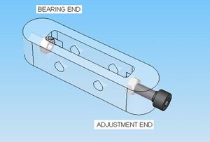
This sub-assembly prevents the z-belt tension from pulling the studdings inwards, which would eat away at the lower corner bracket. A single trapped nut is used as a bearing surface. The other end, tied around the vertical post is adjustable with a trapped nut and an M5 x 20 cap:
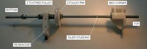
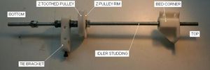
Bottom end assembly
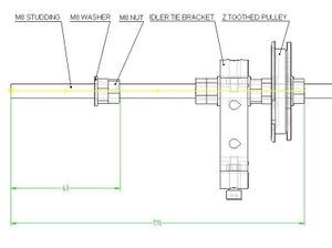
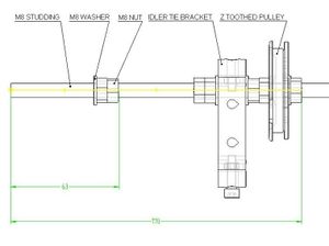
Wind the following set to reach 170 mm up the studding in order (position but do not tighten yet):
- Nut
- Washer
- Z pulley rim
- Z toothed pulley
- Washer
- 2 nuts
- Washer
- Idler tie bracket
- Washer
- 2 nuts
Rest the tie on the studding at the bearing nut end (cap bolt at other end - as in photo). When the tie is in place, you can slot an M5 x 25 bolt through the top of the tie to stop it moving away from the studding, which in turn keeps the bearing nut from dropping out.
Wind the following set to reach 63 mm up the studding (in order):
- 2 nuts
- Washer
Top end assembly
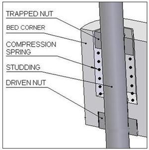
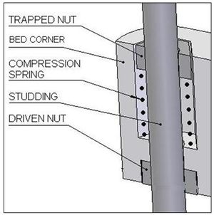
The picture below illustrates the anti backlash spring assembly within the bed corner:
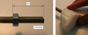
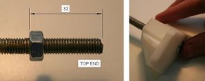
Lightly grease the top 100 mm of the studding & wind down the first nut to 32mm.
Slide the bed corner down to fit onto the nut. Push the spring down the studding inside the bed corner, and hold it in there with the second nut, which should be pushed in to be flush with the bed corner (as in photo).
Now wind the studding to catch the second nut. Continue winding until the top nut of the corner assembly is a good 60mm clear from the end of the studding.
2 M8 nuts and washers should be spare for each sub assembly. These will be used later.
Check to make sure all the bed corners move smoothly, and that none bind significantly to the studding. You may need to release some tension on a spring - compress the spring and undo the free nut a bit. If this doesn't give the required smoothness, don safety glasses and snip turns off the spring until the studding rotates smoothly.
Studding drive
A list of all the parts you need for this section can be found in the BOM for the Cartesian robot.
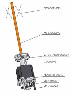
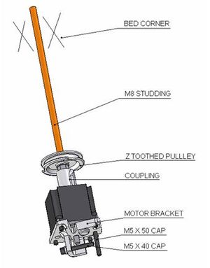
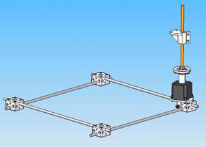
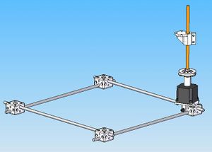
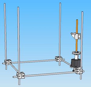
Push the motor bracket onto the datum corner bracket on the bottom XY frame as shown in the diagram:
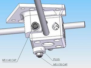
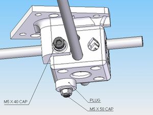
Insert a nut at A into the hexagonal countersink parallel with the short stubbed rod. Pass the M5 x 40 cap from the back through the motor bracket tang (see below) and along the horizontal hole in the corner bracket to meet this nut. Tighten.
Pass the M5 x 50 cap (on a washer) through hole B, down the vertical corner bracket hole and out. Apply a 'Corner bracket vertical bolt plug' (flange inside the hole) and secure with a washer and nut. Tighten.
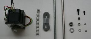
File a 10mm long flat onto the short shaft of the stepper motor, to fit the z motor coupling.
Bolt the motor onto the coupling with 4 M5 caps, nuts and washers (where appropriate), with the long shaft of the motor pointing into the corner bracket. The wires should trail in the direction of the short stub. Tighten.
Insert nuts and grubs into the z motor coupling, and slide the coupling onto the exposed motor shaft. Allow ~ 1 mm clearance between the coupling and the back of the motor. Tighten, ensuring that the grub screw face grips against the flat of the motor shaft.
File a 16mm long flat onto one end of the drive studding to fit the coupling. Before engaging with the coupling...
From the flat end: wind the following set to reach 45 mm up the studding (in order): nut, washer, z pulley rim, z toothed pulley, washer, nut.
At the top end: wind on a bed corner as per studding idler.
Engage the studding into the coupling. The lower M8 nut should come close to, or in actually touching the coupling. If this is the case, tighten the M8 nuts. Tighten the coupling against the studding, ensuring that the grub screw face grips against the flat of the studding.
Installing the Z posts
To find all the parts you need for this section, check out the BOM for the Cartesian robot.
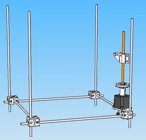
Three long and one short rods (see BOM for lengths) take the majority of the vertical load, and fit into the outer vertical hole for each corner bracket. Assemble the short rod to the datum corner bracket (now the one with the fat motor on it).
Position the nuts and grub screws in the corner brackets as shown below before inserting the rods:
(Note datum position. Ensuring correct grub positioning now will save disassembly time later on)
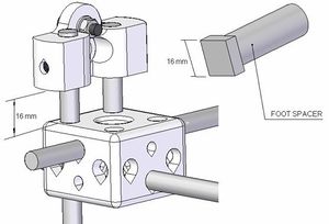
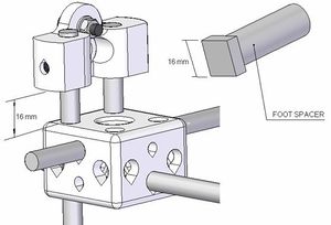
Insert and lock the posts so that they protrude 42mm below the corner brackets (use the foot spacer for this).
Installing the idlers
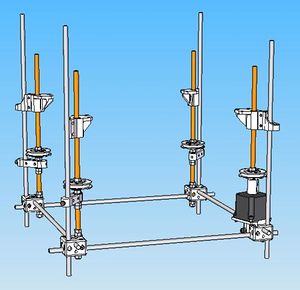
Drop the idler assemblies into the inner vertical holes of of the remaining corner brackets, ensuring the tie brackets loop around the vertical posts.
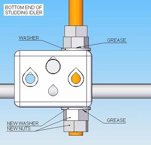
Onto the studding protruding under the corner bracket slide up another washer, and two nuts, applying grease between the washers and the nuts (as shown below).
Lock the bottom two of these four nuts and tighten the upper two so that the studding can spin freely, but have negligible play axially. When this is achieved, lock the upper two nuts. Check again that the studding can rotate freely.
Repeat for the two remaining idler assemblies.
Finally, wind the toothed pulley on the idlers so they are level with the motor pulley. Approximation from side views will do. Tighten these into position.
We'll add the belt later.
Assembling the bed constraints
Wind all the bed corners to approximately the same height, with approximately 60mm of studding sticking out the top.
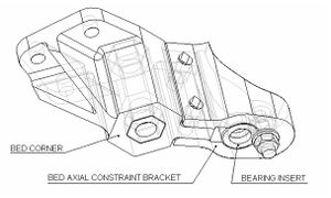
Push the 'Bearing insert (360° running fit)' flush into one of the 'Bed axial constraints'. Lock the bearing insert into the constraint bracket with an M5 x 15 bolt with a nut and washers both sides.
Slide this down the short vertical post (over the datum) to meet the bed corner (as shown in the diagram) and attach to the bed corner with two M5 x 20 caps (as in the picture, the bearing insert should now be level with the lower of the two trapped nuts in the bed corner (this is the primary driver nut)).
There is a bit of horizontal play in fit between the corner and the bracket. This is to make an adjustement to ensure that the studding is parallel with its adjacent post. Make sure this is the case before you tighten.
When finished repeat this procedure for the opposite bed corner, but this time use the 'Bearing Insert (180° running fit)'. Also, do not tighten up the fit between the corner and the constraint bracket just yet.
The remaining two idlers are unconstrained in this manner (doing so would cause over constraint).
Fitting the Bed
To find all the parts you need for this section, check out the BOM for the Cartesian robot.
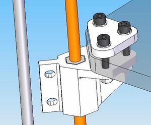
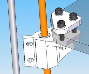
Plonk the bed onto the bed corners and wind the corners up or down to eliminate the jiggle. Slot the M5 x 30 caps through the bed clamp, bed and bed corner as shown below, for all four corners, but don't nut-up just yet (ignore the nuts in the pic):
Now here's the thing. We're just about to tighten the bed onto the corners, but there's deliberately a lot of slop in the holes (I've assumed we don't all have laser guided drilling systems). The mechanically minded out there might understandably feel sick to the stomach that if the studs aren't exactly parallel with their adjacent posts (and at the moment it's going to be hit and miss with so much slop), transmission is going to be a real grind.
Luckily, we've already got a jig to hand: the top XY frame. So before we get serious with the bed bolts, we're going to install the top XY frame.
Mounting the top XY frame
Pre-load the nuts'n'grubs into the corner brackets which will be used to lock to the frame to the posts in the following positions:
Now for the bit which you might hate me for. Apologies, this will be awkward (if the family aren't already involved in RepRap, they might be now). You have to lift up the top XY frame and slot it onto the posts. That's mildly tricky. What's really tricky is not knocking out your pre-inserted nuts. So you've got to be quite gentle here. It helps if you hold the nuts and grubs in with the short lengths of rod used for the Y axis bearings - there are only 3 but you've got a drill bit of the right diameter somewhere - and pull them out once the top layer is aligned with all 4 vertical posts.
Make sure the corner marked TOP is over the DATUM corner.
Slide the frame all the way down so that it rests on the bed, with the studdings running through the inner holes of the corner brackets. This guarantees the studs and post are now parallel, so now you can safely tighten the two nuts and bolts on the bed constraint bracket that you left lose and lock all the bed bolts to the corner brackets.
When complete move the top XY frame so that the top face of the bottom frame corner brackets and the bottom face of the top frame corner brackets are 355mm apart. Use the 355 mm rod as a spacer and lock off the grub screws, with a bit of welly. This is exact spacing is less easily achieved for the datum corner because the bed constraint bracket and the motor bracket are in the way. You will have to estimate this using the spacer from the side .
Attaching the base diagonals
To find all the parts you need for this section, check out the BOM for the Cartesian robot.
Slot the diagonal tie brackets on at each end of the studding (diagonal bottom) via the top hole. Brace the tie brackets near the end of the studding with an M8 nut and washer each side. Insert the trapped nut into the remaining central hole. Repeat for the other end of the studding:
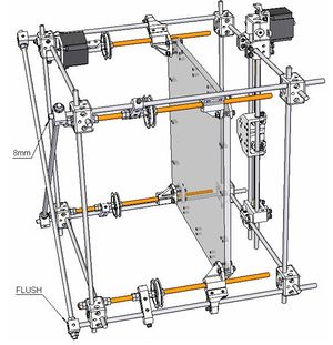
Make a second lower diagonal assemblies. Carefully roll the rig onto its side and fit the diagonals to the Z posts as per diagram:
The lower diagonal tie bracket should be flush with the end of the post. Lock the tie brackets to the posts, tighten the bracing M8 nuts and carefully right the rig.
Setting the z idler ties
As mentioned before, the z idler tie brackets prevent the belt tension from pulling the studding inwards, which would eat away at the lower corner bracket.
Now rotate the bolt in the idler tie bracket until it touches the post. Then rotate by half a turn more, pulling the studding slightly outwards. This relieves any pressure of the studding on the inside surface of the lower corner bracket vertical hole. Give it a wiggle to check it for your self. Your Z transmission is now ready to be given a belt.
Z belt
For this job you will need:
- The belt splicer
- G-clamp
- Scalpel
- Superglue
- 1 belt (6mm wide, tooth period 2.5 mm) at least 1750 mm long (if you can't get one that long will need to splice two shorter ones together...).
To make the Z belt continuous, we will need to splice a belt together:
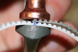
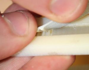
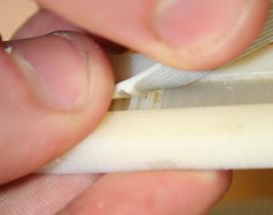
Teeth have been cut off the bottom belt end, and then the bottom belt has been glued onto the back of the top belt end. The deliberate missing tooth makes it run smoother through the pulleys.
A special mould (the belt splicer) is needed to ensure that when the ends are spliced, the teeth at both ends are still at the same period.
Double check your Z idler pulleys are the same height as the drive pulleys. Just looking at the rig from each side will suffice.
Take the belt and wrap it around your Z pulleys. Pull the belt ends together as tight as you can, as it would be when it's spliced..
You need to mark bottom belt where the end of the top belt meets it. This mark was made after pulling the bottom belt past the top end as far as I could, and then marking it down one tooth further (making the belt even tighter after it was spliced).
This general "as tight as you can, and then one tooth more" rule seems to work well (a slack belt will skip, too tight a belt will cause high friction).
End your mark around the back of the bottom belt.
A ten tooth length of splice works well, so cut the bottom end ten teeth down (to the right in that photo) after, and including, the mark.
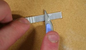
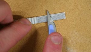
Now you need to shave the teeth off the bottom belt with a scalpel. It's tricky, so wear gloves, safety glasses in case the blade pings off and do it on wood so you don't blunt the blade unnecessarily. Scalpels cut best by moving backwards and forwards rather than slashing. Whilst slashing the meat of the teeth off will work, it certainly won't when you get down to the wire reinforcing - the slashing tends to skip into violent digs which cut wire. And then you've lost your belt (believe me I know).
Take eleven teeth off the end because we want a missing one. Make sure you shave down to the gleaming wires.
Rough up the back of the top belt with the file, or shave it down to the wire if it's a thick one.
Now, reloop the belt around your Z idlers. Don't put them over the pulleys yet, you'll never be able to glue it together under such tension, just make sure it's around all four studdings and inside the posts. This is really important. Ignore the clamp in the photo below for a minute, just make sure your belt follows a similar path.
Put the top belt end (the roughed up back one, with teeth) teeth down into the female belt splicer, half way up its length. Make sure the teeth are firmly pushed into the mould.
Put the bottom belt on top of that, making sure that the mark overlaps the last tooth of the belt in the mould, and that there will be a missing tooth when glued together as shown here:
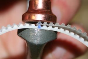
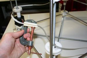
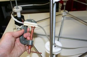
When happy, push the belts firmly into the mould. Peel back the upper belt end and spread superglue over the back of the one underneath. Now push the upper belt back down onto the glue, and G-clamp using the male section of the mould to ensure the pressure goes to the right place.
Make a cup of Earl Grey tea and think British thoughts.
After the glue's dried, you need to put the belt on the pulleys. Simply slacken off a rim nut about 40 mm. Lift the rim, and tuck the belt next to the studding, in between the rim and the pulley. Load the belt onto the other three pulleys. Pull the belt round and as you do, slip it onto to your remaining pulley. Put the rim back and you're done.
(By disengaging the belt it is possible to spin the pulleys individually, thus tweaking the bed levels. This is important later, so remember the rim detachment trick.)
Assembling the Y axis
To find all the parts you need for this section, check out the BOM for the Cartesian robot.
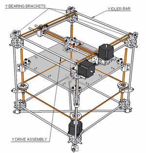
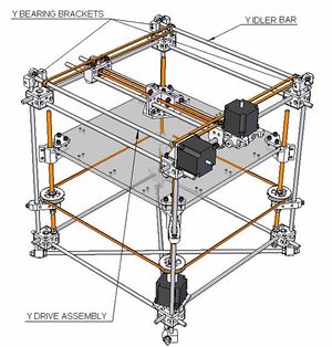
Now for the Y, which comprises of a drive rod and idler rod suspended by 3 bearing brackets and a motor bracket:
Bearing housing assemblies
First make the drive bearing:
Push in the bearing insert (360 run) and lock in with an M5 x 15 cap.
Load the trapped nuts into the barrels.
Push the Y post rod up into the right hole and make flush with the top of the bracket and lock off.
Now make the two idler bearing assemblies. It's exactly the same as above, but you need bearing inserts (360 jam) instead, and one of the assemblies needs to have its post in the left barrel instead of the right.
Installing the bearing housings
Load 3 sets of nuts and grubs into the top corner brackets as shown below:
Slide the drive housing into position at corner 1 (pic above), slotting the vertical post into the empty barrel (as in pic below).
The bottom face of the bearing bracket needs to be 16 mm above the top face of the corner brackets. Use the base of the foot spacer to help you. Lock off all grubs when set.
Repeat for the idler brackets. Check the cap head side of the bracket is facing the exterior for all brackets.
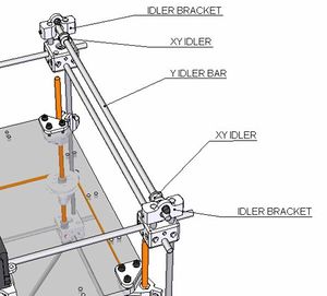
Inserting the Y idler rod
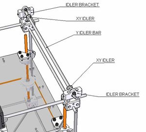
Remove a bearing inserts from one of the idler brackets. Push the XY idler through the hole, catch 2 XY idlers and jam into the far idler bracket. Replace the bearing insert with a even amount of idler rod protruding outside each of the idler brackets.
Assembling and mounting the Y drive
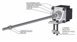
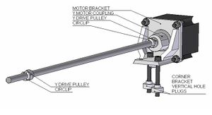
File a flat onto the major motor shaft to fit the Y coupling. Hack this motor shaft to a length of 13.5 mm.
File a flat on the end of the Y drive rod to fit the length of the Y coupling, no more.
Now file a flat up the length of the bar to file the profile of the Y blade used in the moulding of the Y toothed pulleys. It needs to extend 400mm from the coupling end! Now cool it or you might melt your Y toothed pulleys. This might seem like a ball-ache, but it only takes 10 minutes with a file and is necessary so you can slide your Y toothed pulleys into position. There are two alternatives if 400mm sounds like too much of an effort, but they both have slight mechanical disadvantages:
- Just file the flats where needed and push the toothed pulleys over the full round sections into position. Risk: deformed toothed pulleys.
- File the flat from the opposite end of the coupling. Risk: the resulting flat section of the shaft rotating in bearing might wear the bearing quicker.
First, mount the motor bracket firmly onto the 'TOP' corner bracket (the stub and z post might take a bit of force to fit into their respective holes). Now drop 2 M5 x 50 caps down the vertical holes in the motor bracket (shown above), through the corner bracket. Use the corner bracket vertical hole plugs and tighten up these bolts.
Load nuts and grubs into the coupling. Fasten the coupling onto the motor shaft, leaving 1 mm clearance, ensuring that the grub tightens against the flat of the motor shaft.
Take the Y drive rod and slide on the Y drive pulleys, to the approximate positions shown in the above picture. Clip on the circlips against the unflanged end of each drive pulley.
Push the rod into the coupling as far as it will go and lock it off, ensuring that the grub tightens against the flat of the rod.
Slide the rod/coupling/motor assembly through the back of the motor bracket. Bolt the motor onto the back of the motor bracket with M5 x 15 caps, wires trailing down (wrt pic below).
Super glue the Y drive pulleys in place, making sure that they line up with the centre of their respective belt clamps on the X axis.
Finally, fit the belts. Leave a bit of excess at the belt clamps - this will be useful to grip if you need to re-tension the belts later.
Side diagonals
To find all the parts you need for this section, check out the BOM for the Cartesian robot.
Now it's time to assemble all your side diagonals (as per the base diagonals) and put them on the rig. Fit the 20 mm stubs first, then the 28 mm. Access by the Y motor is tight; the studding needs to be under the horizontal rod to which you are attaching it.
Installing the extruder and fan
You need to have assembled the extruder first. Instructions on how to do this are here.
Look at the rig with the motors all on your left side. Now we'll fit the extruder and fan to the near-right-side of the carriage.
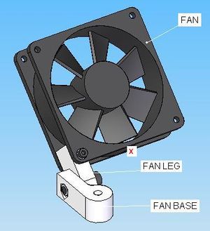
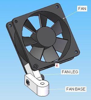
Start by assembling the fan.
From this picture, ensure the fan direction blows downwards (there's usually an arrow on the casing), and the wires exit from the side marked x.
Bolt the fan to the fan leg using the M3 x 30 cap.
Bolt the fan leg to the fan base using the M5 x 20 cap.
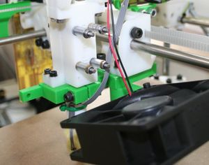
Take a look a the photo below. Fix the extruder onto the base of the carriage using two M5 x 20 caps and one M5 x 30 cap. The M5 x 30 cap should pass through the fan base too, and pick up the trapped nut within, as shown in the photo:
Squaring up
Now to ensure you're making squares not parallelograms.
Z axis
Move the bed up to just below the tip of the extruder nozzle (by pulling on the engaged Z belt).
Disengage the Z belt by unscrewing an idler rim and popping the belt off the teeth.
Now move the extruder to its four extreme positions. At each position adjust the height of each bed corner by rotating its respective studding. Do this until the bed is equidistant from the extruder nozzle at all four points.
Re-engage the belt.
X axis
Insert the X axis square jig onto the end stubs of the X axis (at the idler end).
http://picasaweb.google.co.uk/VikOlliver/RepRap02/photo#5102851967039491186Tighten the Y belt nearest the motor end.
Push the jig up so that the flats touch the side of the XY frame and lock off.
Tighten the remaining Y belt, making sure the jig stays square against side of the XY frame.
Lock off the belt and remove the X axis square jig.
Congratulations, that's the end of the structural part of the Cartesian robot! Now you're ready to fit the electronics.
Z Axis trouble shooting
To see how to fix your unforgiving Z axis, click ZAxisTroubleShooting.
