Software
|
English • العربية • български • català • čeština • Deutsch • Ελληνικά • español • فارسی • français • hrvatski • magyar • italiano • română • 日本語 • 한국어 • lietuvių • Nederlands • norsk • polski • português • русский • Türkçe • українська • 中文(中国大陆) • 中文(台灣) • עברית • azərbaycanca • |
About | Getting Started | RepRap Projects | Hardware | Software | Community
Contents
Software
The software toolchain can be roughly broken down into 3 parts:
- CAD tools.
- CAM tools.
- Firmware for electronics.
The RepRap project advocates for free software, but acknowledges that there are other choices.
Modeling (CAD)
Computer Aided Design, or CAD, tools are used to design 3D parts for printing.
CAD tools in the truest sense are designed to allow you to easily change and manipulate parts based on parameters. Sometimes CAD files are referred to as parametric files. They usually represent parts or assemblies in terms of Constructive Solid Geometry, or CSG. Using CSG, parts can be represented as a tree of boolean operations performed on primitive shapes such as cubes, spheres, cylinders, pyramids, etc.
Free/Libre/Open Source Software (FLOSS) applications that fall into this category would be OpenSCAD, FreeCAD and HeeksCAD and more. Examples of proprietary and fully parametric CAD tools are PTC Creo (formerly PTC Pro/Engineer), Dassault Solidworks, Autodesk Inventor and more.
Typically in such programs the geometry is stored in a feature tree where the dimensions can be modified numerically, and the geometry is then regenerated with great precision. The geometry is a mathematical representation where, for example, a circle is generated from its center, radius and plane parameters (hence, "parametric"). No matter how much you zoom in, a circle is still curved, and the CAD program has no problem finding its center when you click on it. This can be quite beneficial when making drawings with dimensions between the circle and sections that need to be concentrically removed.
Some modelling software approached modelling with the use of 3D Polygon mesh. These applications tend to be used more for special effects and artistic applications. They also seem to be a little more user-friendly. FLOSS-apps in this category would be Blender and Art of Illusion. Proprietary tools are Autodesk 3ds Max, Autodesk Alias, SketchUp and more.
Furthermore, you can create forms with just a web-browser at certain websites, such as TinkerCAD.com (easy) or 3DTin.com (more sophisticated), those permit you to download the resulting geometry.
Some of the tools mentioned above also use parametric data to generate the geometries, but a lot just register the positions of the vertices of the polygons making up the models. Some use parameters to generate the geometry but then drops that data once the vertices are placed. A curve is thus actually an approximation, generated from a number of straight lines between points. As such, those tools are better suited for design where the precision of dimensions are less important than looks and ease of use.
If you want to print as less possible material as possible; design parts optimised by volume in function of strains, you may use topology optimization through non-commercial-use-only software such as Topostruct (see sawapan.eu website), BESO, or free-open-source-use such as Topy, a topology optimization software written in Python by the brilliant William Hunter (see google code topy page).
It might be useful to have a lattice engineering software, that will create a support of your part or fill the part to save material. One of the most used is Materialize Magics, but there is also Netfabb. Both are proprietary software's, not free.
- File Formats *
Most of the time 3D software apps save their files in an application-specific format, which in the case of proprietary CAD tools usually are frequently changed and heavily guarded trade secrets.
There are very few interchangeable CAD file formats. The two most widely used interchangeable CSG file formats are STEP and IGES. Both strip the geometries from parametric data and offer only "dead" solids. Features can be added and removed, but the base shape is locked. There is to date no industry-wide interchangeable file format that retain parametric data.
The most widely used interchangeable mesh file format is STL. STL files are important because, as we will see below, they are used by CAM tools.
Mesh files cannot be converted into CSG file formats because they contain no parametric data - only the coordinates of the polygon vertices that make up the solid volume. However, CSG file formats can be converted into mesh file formats.
Thus, if you're designing a part, it's a good idea to design it using a CSG CAD application and save and distribute its original parametric file along with generated STL files.
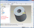
Parametric file format
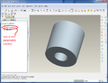
STEP export format
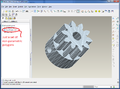
STL mesh format


Slicers (CAM)
Computer Aided Manufacturing, or CAM, tools handle the intermediate step of translating CAD files into a machine-friendly format used by the RepRap's electronics. More info is on the CAM Toolchains page.
In order to turn a Design part into a machine friendly format, CAM software needs an STL file. The machine friendly format that is used for printing is called G-code. Early versions of RepRaps used a protocol called SNAP but industry standard G-codes are now used. To Convert STL files to G-code, you can use one of the following programs:
- MatterSlice (Fast and full featured - works with MatterControl)(open source)
- Skeinforge (Dated solution)(Still one of the best and highly recommended for accurate prints
- Cura (Also includes G-Code sender)(Extremely fast and accurate)
- Slic3r (Popular solution for most RepRappers)(Lots of bugs in every release)
- Kisslicer (Fast and accurate with very few bugs)(Closed source)
- RepSnapper
- RepRap Host Software
- X2sw
- SuperSkein
- SlicerCloud (Online Slic3r solution)
- Simplify3D (All-In-One Paid Suite)
- Cloud3Dprint (Slice your 3D files for over 150 supported printers or enter your own customized 3d printer parameter)
The STL to G-code conversion slices the part like salami, then looks at the cross section of each slice and figures out the path that the print head must travel in order to squirt out plastic, and calculates the amount of filament to feed through the extruder for the distance covered.
(Normally you don't need to repair, edit or manipulate STL files directly, but if you do, you might find the software at Useful Software Packages#Software for dealing with STL files useful).
- G-code sender *
To send the G-code files to a microcontroller's g-code interpreter, you need to either to:
- Load the G-code file on an memory card (typically SD card) if supported.
- Historically it was more common to Drip-feed the G-codes (usually a line at a time) over a serial port (RS-232 or TTL level, often used with a USB converter) or a direct USB connection using one of the following programs on your workstation, this has become more common again with the use of klipper
Some of the options are cross platform while others will only work with certain operating systems or prefer specific integrated firmware interpreters.
Machine Control
After you have your G-code file, you have to run it through a G-code interpreter. This reads each line of the file and sends the actual electronic signals to the motors to tell the RepRap how to move. There are two main ways to run a G-code interpreter:
1) The most common way is to interpret G-code in the firmware of a microcontroller. Typically, the microcontroller is AVR-based which is what's used in the Arduino. In order to transfer the g-codes to the microcontroller, you need a way to send the g-code to the microcontroller. See below for more details.
2) The alternate way is to interpret G-code using software that runs on a multi-purpose O/S such as linux. Two examples are EMC and Redeem. With these types of interpreters, THERE IS NO GCODE SENDER. The operating system communicates directly with special hardware that controls the motor signals. For EMC, it typically uses the computer's parallel port. For Redeem, it uses the PRU built into the Texas Instruments ARM CPU on the Beaglebone Black.
G-codes
After your microcontroller has its firmware loaded, it is ready to accept G-codes via the software-emulated RS-232 serial port (aka COM port). This port shows up when you plug in your arduino to the PC via USB. You can either use a program to send these G-codes over the serial port or you can type them in by hand if you fire up a plain-old terminal application like hyperterm or minicom. If you use a program, they generally take files in gcode format.
For all available firmwares see List of Firmware. The following is a brief list of the most popular firmware:
Firmware
The firmware files are usually packaged as source code for an Arduino IDE project. Arduino source code consists of a bunch of PDE (or as of Arduino ver 1.0, INO) files along with some extra .cpp and .h files thrown in. The Arduino IDE compiles the source code into a single .hexfile. When you click on the upload icon in the Arduino IDE, it uploades the .hex file to the electronics.
