RAMPS 1.4/ru
|
English • العربية • български • català • čeština • Deutsch • Ελληνικά • español • فارسی • français • hrvatski • magyar • italiano • română • 日本語 • 한국어 • lietuvių • Nederlands • norsk • polski • português • русский • Türkçe • українська • 中文(中国大陆) • 中文(台灣) • עברית • azərbaycanca • |
Release status: Working

| Description | RepRap Arduino Mega Pololu Shield
Arduino MEGA based modular RepRap electronics.
|
| License | |
| Author | |
| Contributors | |
| Based-on | |
| Categories | |
| CAD Models | |
| External Link |
Contents
- 1 Основное отличие от предыдущих версий
- 2 Безопасность
- 3 Сборка и монтаж
- 3.1 Пайка компонентов
- 3.2 Требуемые инструменты
- 3.2.1 Монтаж Платы
- 3.2.1.1 Конденсатор C2 - 100nF
- 3.2.1.2 Зеленый светодиод LED1
- 3.2.1.3 Красные светодиоды LED2, LED3, LED4
- 3.2.1.4 Резисторы R13, R14, R15 - 10 Ohm
- 3.2.1.5 Резистор R12 - 1K
- 3.2.1.6 Резисторы R23, R24, R25 - 1.8K
- 3.2.1.7 Резисторы R1, R7, R11, R21, R22 - 4.7K
- 3.2.1.8 Резисторы R16, R17, R18, R19, R20 - 10K
- 3.2.1.9 Резисторы R2, R3, R4, R5, R6, R8, R9, R10 - 100K
- 3.2.1.10 Конденсаторы C1, C5, C8 - 10uF
- 3.2.1.11 Конденсаторы C3, C4, C6, C7, C9, C10 - 100uF
- 3.2.1.12 Окончание пайки SMD элементов
- 3.2.1.13 Пины джамперов
- 3.2.1.14 Разъемы драйверов двигателей
- 3.2.1.15 Диоды D1, D2
- 3.2.1.16 Предохранитель F1 - MFR500
- 3.2.1.17 Предохранитель F2 - MFR1100
- 3.2.1.18 Полевые транзисторы - Q1, Q2, Q3
- 3.2.1.19 Разъем для подключения нагреваемого стола и экструдеров
- 3.2.1.20 Разъем питания
- 3.2.1.21 Разъемы для Arduino MEGA
- 3.2.1.22 Кнопка сброса
- 3.2.1.23 Проверка
- 3.2.2 Плата драйверов шагового двигателя
- 3.2.3 Оптические концевики
- 3.2.4 Механические концевики
- 3.2.5 Put the connectors on the motor wires
- 3.2.6 Thermistor Wires
- 3.2.7 Pololu carriage
- 3.2.1 Монтаж Платы
- 4 Final Setup
- 5 Firmware and Pin Assignments
Основное отличие от предыдущих версий
В RAMPS 1.4 конденсаторы и резисторы размещены в SMD варианте, что позволило разместить больше пассивных компонентов. Но мы остановились на больших размерах, что бы упростить монтаж


Безопасность
Перед подключением электричества даже 12 Вольт, Вы должны принять все меры для предотвращения пожаров. Если все же вероятность пожара существует, то проверьте работоспособность своего детектора дыма smoke detector. Нет детекторов? Купите :)!
Сборка и монтаж
Пайка компонентов
Требуемые инструменты
Вы должны иметь: Паяльник или паяльную станцию, хороший пинцет, припой
Желательно иметь: Хорошую лупу
Монтаж Платы

Пайка RAMPS 1.4 включает в себя как пайку элементов поверхностного монтажа(SMD), так и пайку элементов сквозного монтажа( разъемы, транзисторы и предохранители).
Пайку можно осуществить несколькими способами. Используйте самый удобный для Вас. Все SMD элементы на данной плате двухконтакные, так что, при наличии нормального паяльника (все же лучше паяльной станции), пайка не представляет труда. Нанесите немного припоя на контактные площадки. Установите пинцетом элемент и вновь разогрейте припой на площадке -после чего элемент встанет на место. Так же можно паять при помощи паяльной пасты, разогревая плату в духовке, плите или специальных печах HotplateReflowTechnique
Сначала припаяйте SMD компоненты, затем предохранители, резисторы и разъемы на верхней части платы, ни и закончите пайкой контактов с обратной стороны
Конденсатор C2 - 100nF

Можно припаять в любой ориентации. Полярность не имеет значения.
Зеленый светодиод LED1

Контакт светодиода маркированный зеленой точкой к контактной площадке маркированной значком "+" на печатной плате.
Красные светодиоды LED2, LED3, LED4

Контакт светодиода маркированный зеленой точкой к контактной площадке маркированной значком "+" на печатной плате.
Резисторы R13, R14, R15 - 10 Ohm

Можно припаять в любой ориентации. Полярность не имеет значения.
Резистор R12 - 1K

Можно припаять в любой ориентации. Полярность не имеет значения.
Резисторы R23, R24, R25 - 1.8K

На печатной плате они помечены как 1К, но мы используем резисторы с более высоким сопротивлением для увеличения предельного напряжения. Можно припаять в любой ориентации. Полярность не имеет значения.
Резисторы R1, R7, R11, R21, R22 - 4.7K

Можно припаять в любой ориентации. Полярность не имеет значения.
Резисторы R16, R17, R18, R19, R20 - 10K

Можно припаять в любой ориентации. Полярность не имеет значения.
Резисторы R2, R3, R4, R5, R6, R8, R9, R10 - 100K

Можно припаять в любой ориентации. Полярность не имеет значения.
Конденсаторы C1, C5, C8 - 10uF

Эти конденсаторы должны быть правильно ориентированны.Совместите закругления базы конденсатора с рисунком на плате и припаяйте.
Конденсаторы C3, C4, C6, C7, C9, C10 - 100uF

Эти конденсаторы должны быть правильно ориентированны.Совместите закругления базы конденсатора с рисунком на плате и припаяйте.
Окончание пайки SMD элементов


Если вы используете для пайки печь или духовку, то пора отправить плату на нагревание. Если Вы паяли паяльником или паяльной станцией, то пайка окончена
На данном этапе проверьте еще раз качество пайки SMD элементов, потом переделать будет гораздо труднее
Пины джамперов

Припаяйте 1 разъем 1x6, 6-1x4, и 7 - 2x3.
Разъемы драйверов двигателей

Припаяйте разъемы мама для установки драйверов шаговых двигателей
Диоды D1, D2


Детали должны быть правильно ориентированны в соответствии с рисунком на плате. Однако, в связи с имеющимися случаями неправильной маркировки диодов в Китае - проверьте полярность тестером, не доверяйте полностью полоске на диоде.
D1 should only be installed if the 5A rail is powered by 12V. It can be omitted and the Arduino will be powered from USB. You will want D1 installed if you add components to print without a PC. To reiterate, D1 MUST be omitted if you are powering the 5A rail by more than 12V, or the power is not absolutely clean, otherwise you may damage your ramps.
Предохранитель F1 - MFR500
Это маленький желтый предохранитель. Устанавливать можно в любой полярности. Так как это одна из наиболее высоких деталей, то лучше паять в самом конце.
Предохранитель F2 - MFR1100
Это большой желтый предохранитель. Устанавливать можно в любой полярности. Так как это одна из наиболее высоких деталей, то лучше паять в самом конце.
Полевые транзисторы - Q1, Q2, Q3

Ориентировать согласно картинке на плате.
Разъем для подключения нагреваемого стола и экструдеров

Устанавливается, так чтобы провода из разъема выходили на край платы
Разъем питания

Ориентируйте разъемом к краю платы
Разъемы для Arduino MEGA


С нижней части припаяйте разъемы для подключения Arduino MEGA. Чтобы правильно установить их, вставьте их в Arduino MEGA и в плату. Проявите аккуратность и не перегрейте при пайке иначе можно перегреть Arduino MEGA, не пропаивайте сразу соседние пины, паяйте в разных местах.
Кнопка сброса

Установите кнопку согласно рисунку на плате, кнопкой в краю платы.
Проверка
Проверьте качество пайки, контакт, наличие замыканий соседних дорожек, очистите плату от лишнего флюса.
Плата драйверов шагового двигателя
- В каждом драйвере из пяти должны быть установлены перемычки, регулирующие размер шага :
 jumper   Yes/No  размер шага
 1     2    3
 no   no    no    полный шаг
 yes  no    no    полушаг
 no   yes   no    1/4 шага
 yes  yes   no    1/8 шага
 yes  yes   yes   1/16 шага
Большинство использует микрошаг 1/16 (все перемычки установлены)
- Вставьте 2 восьмипиновых разъема в платы драйверов.
- Вставьте платы драйверов с разъемами в основную плату
- Быстро пропаяйте, чтоб не перегреть разъемы и платы. Не паяйте сразу соседние пины, имейте терпение чтобы дать остыть плате
- К микросхемам драйверов приклейте на термоклей радиаторы.
Оптические концевики
Инструкции по изготовлению оптических концевиков версии 2.1 можно найти здесь here on the reprap opto page, а так же here.
- Пока строите принтер, в зависимости от размещения электроники и станка определитесь с необходимой длинной кабеля..

- Отрежьте кабель необходимой длинны
- Обожмите и пропаяйте разъемы на конце каждого провода. (Если нормально обжать, нормальным инструментом, то паять и не надо)
- Провод не менее чем 2,54 х3( рекомендации разработчика, хотя мне кажется, что 0,5 будет вполне достаточно).
- подключите хотя бы один концевик.
- Пока строите принтер, в зависимости от размещения электроники и станка определитесь с необходимой длинной кабеля..


| Разъем платы | |
| Сигнал (S) | Белый |
| GND (-) | Черный |
| VCC (+) | Красный |
| Разъем концевика | |
| VCC (+) | Красный |
| Сигнал (S) | Белый |
| GND (-) | Черный |
Механические концевики

Рекомендуемые прошивки используют 2-х проводные механические концевики.
Найдите на плате область помеченную "endstops" соответственно для каждой из осей X, Y, и Z pairs of pins и выполните следующие действия:
- Соедините контакт помеченный на плате"S" с контактом "NC" микропереключателя.
- Соедините контакт помеченный на плате "GND" с контактом "C" микропереключателя.
Note: The latest firmware such as Marlin seems to use NO as the default pin on the switch. Otherwise you may need to invert the endstops in the firmware. You can use M119 to check your endstops status.
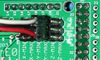
Put the connectors on the motor wires
- solder a female connector to the ends of each wire.
- use the 2.54mm 1x3 housing.
- Shown is the type used for servos in RC projects. See Stepper Motors for info on motors.
Thermistor Wires
Use a 2 pin 0.1" connector to terminate the thermistor wires.
- Connect the cable so the 2 wires go to T0
- Connect the 2 heater wires to D10 (E0H on older boards) and the + connection above it.
- If changing to an unverified firmware it is best to verify heater circuit function with a meter before connecting heater to prevent damage to the extruder.
Pololu carriage

This section assumes you are using Pololu, but there are other options. Insert two 1x8 pin headers into the board. If you bought a kit with one 16 pin header, simply cut it so that you have two 1x8. Make sure that the side with the labels has the long ends of the posts, and the side you want to solder is the side with the heat sink. Doing this backwards will cause you not to see the labels and will most likely not fit. Remember to apply a heat-sink to the largest chip on the back.
Final Setup
Pre-Flight Check
If you think you may have mistakes you can install only one stepper driver during initial testing and risk only one stepper driver.
The trimpot on the stepper drivers controls the current limit. Turn it all the way down (counter clock wise) and back up 25%. Be careful to not force the trimpot, it is delicate. You will need to fine tune the current limit later. Note that it is allways giving the motors that much power, even when not moving, so if your stepper motor drivers are getting hot, you may want to turn it down slightly.
Connect the minimum endstops for X,Y, and Z
Connect Motors (Do not disconnect or connect motors while powered; if the connection is loose, this will cause the motors to spazz and possibly kill your stepper driver.)
You may want to use this code to test all the electronics before installing any of the suggested firmwares.
Install firmware (More info below). Firmware flashing can be done without 12V power supply connected.
Wiring
It is relatively simple to wire up the RAMPS. Just add the extruder heating coil wire to D10, the thermistor to the two T0 pins on middle right right, and wire up the steppers and endstops. From left to right, wire all of the stepper motor's wires as red, blue, green, and black or red, green, yellow, blue into the pins next to the Pololus. When you connect the wires to the endstops (if you are using 3 endstops, plug them into the MIN (-) slots), make sure you match the labels.

Note that tesla & tonok firmware use d9 and sprinter and johnny/tonok use d10 for the extruder hot end.
Warnings
Reversing +/- or otherwise incorrectly connecting power can destroy your electronics and cause fire hazard.
Incorrectly inserting stepper drivers will destroy your electronics and cause a fire risk. Always make sure power and USB is disconnected when removing or adjusting stepper drivers. Always make sure to insert drivers in correct orientation and in the socket correctly.
The endstop pins are Signal - GND - VCC, instead of the VCC - Sig - GND like the rest of RepRaps boards. Make sure to wire them correctly. This is done to allow squeezing fatter traces on the printable board.
Connecting Power
Connect your 12V power supply to the RAMPS shield. Reversing +/- or otherwise incorrectly connecting power can destroy your electronics and cause fire hazard.
The bottom pair of connectors marked 5A power the stepper drivers and Extruder heater/fan (D9, D10). The source should be rated a minimum of 5A.
The pair of connectors above marked 11A power a Heated Bed, or other output (D8). The source should be rated a minimum 11A (if both power rails are connected to the same supply it should have a minimum rating of 16A).
The barrel connector, on the Arduino MEGA, will NOT power RAMPS and will not provide power to the stepper motors, heated bed, etc.
The power connector plug may not be obviously labeled, looking at the power connection the positive is on the left and the negative is on the right of the plug.
Power Supply
RAMPS is quite happy with the 12 V line from PCPowerSupply. Or you can hack up a 12V laptop power supply, or other 12 V "wall wart" power supply. Be sure that the power can output 5A or greater. Additional 11A may be needed for heated bed support.
See Connecting power above.
The 3 pins next to the reset switch are meant to optionally connect to your PSU.
The PS_ON pin is intended to switch your power supply on and off. Many firmwares support pulling this pin low with M80 command to turn the power supply on, and M81 to turn it off. This behavior is desired for ATX power supplies and can be modified in firmware to support 5V high power supplies like those borrowed from an Xbox.
Without D1 installed, or when the 12VIN is not connected, the Arduino gets its power from USB. If you want your kit powered without USB connected you need to solder in D1 OR connect VCC to your PSU.
The VCC pin can be connected to your ATX's 5Vsb to continuously power the Arduino from your ATX power supply. You will want to make sure that D1 is not installed or cut out. The Arduino is not designed to be powered directly on the VCC rail and the VIN pin at the same time.
The 5V pin in that connector on RAMPS only supplies the 5V to the auxiliary servo connectors. It is designed so that you can jumper it to the VCC pin and use the Arduino's power supply to supply 5V for extra servos if you are only powered from USB or 5V. Since there is not a lot of extra power from the Arduino's power supply you can connect it directly to your 5V power supply if you have one. You can also leave this pin not connected if you have no plan to add extra servos.
Maximum Input Voltage
Power Supply without diode
The 1N4004 diode connects the RAMPS input voltage to the MEGA. If your board does not have this diode soldered in, you can safely input as much as 35V. (The pololus can do up to 35V)
Power Supply with diode
If your board has a 1N4004 diode soldered in, do not apply more than 12 V to it. Original flavor Arduino Mega are rated to 12 V input. While Arduino Mega 2560 can take 20 V, it is not recommended.
Firmware and Pin Assignments
RAMPS 1.4 uses the same pin definitions as 1.3.
You will need the Arduino software at http://www.arduino.cc/en/Main/Software to upload the firmware to Arduino Mega. Arduino MEGA 2560 Rev3 requires Arduino software version 0023.
Sprinter and Marlin are popular and stable firmwares for RAMPS as of 3/28/2012. Pronterface is a cross platform printer control program that can be used for testing/printing.
Working preconfigured sprinter firmware can be downloaded at http://ultimachine.com/sites/default/files/UltiMachineRAMPS1-4Sprinter.zip . Mechanical is in the folder ending with ME, optical endstop firmware is in the folder ending in OE.
Others (Need pins set in Firmware as below):
- mechanical endstops (now the default ultimachine.com option) require #define OPTO_PULLUPS_INTERNAL 1 to be added to configuration.h if not there by default.
Here are the pin definitions for this board.
// For RAMPS 1.4
#define X_STEP_PIN         54
#define X_DIR_PIN          55
#define X_ENABLE_PIN       38
#define X_MIN_PIN           3
#define X_MAX_PIN           2

#define Y_STEP_PIN         60
#define Y_DIR_PIN          61
#define Y_ENABLE_PIN       56
#define Y_MIN_PIN          14
#define Y_MAX_PIN          15

#define Z_STEP_PIN         46
#define Z_DIR_PIN          48
#define Z_ENABLE_PIN       62
#define Z_MIN_PIN          18
#define Z_MAX_PIN          19

#define E_STEP_PIN         26
#define E_DIR_PIN          28
#define E_ENABLE_PIN       24

#define SDPOWER            -1
#define SDSS               53
#define LED_PIN            13

#define FAN_PIN            9

#define PS_ON_PIN          12
#define KILL_PIN           -1

#define HEATER_0_PIN       10
#define HEATER_1_PIN       8
#define TEMP_0_PIN          13   // ANALOG NUMBERING
#define TEMP_1_PIN          14   // ANALOG NUMBERING
Source
| FILE ID# | TYPE | DESCRIPTION | DOWNLOAD |
|---|---|---|---|
| File:ArduinoMegaPololuShield.zip | Eagle Files | These are the files you need to make the board.(Use the File: link to the left to access older versions of the file.) | media:ArduinoMegaPololuShield.zip |
| File:RepRapjr.lbr | Eagle Libraries | The components used in this board are here. see Eagle_Library | media:RepRapjr.lbr |
Список деталей
| Обозначение | Наименование деталей | Количество | Фото | Ссылка в Терраэлектронника | Возможная замена |
|---|---|---|---|---|---|
| U1 | Ардуино Мега | 1 | Ардуино 2560 или клоны | ||
| U2,U3,U4,U5 | Pololu драйвер шагового | 4 | Драйверы StepStick или аналогичные на A4988, A4983 | ||
| C2 | Конденсатор пленочный SMD 100nF в корпусе 0805 номинальным напряжением выше, чем планируется использовать для питания | 1 | |||
| C1,C5,C8 | Конденсатор электролитический SMD 10uF в корпусе 0405 больше 5вольт | 3 | |||
| C3,C4,C6,C7,C9,C10 | Конденсатор электролитический SMD 100uF в корпусе 0605 номинальным напряжением выше, чем планируется использовать для питания | 6 | |||
| R1,R7,R11,R21,R22 | Резистор SMD в корпусе 0805 сопротивлением 4.7K точностью не менее 1% | 5 | |||
| R2,R3,R4,R5,R6,R8,R9,R10 | Резистор SMD в корпусе 0805 сопротивлением 100K точностью не менее 1% | 8 | |||
| R12 | Резистор SMD в корпусе 0805 сопротивлением 1K точностью не менее 1% | 1 | |||
| R23,R24,R26 | Резистор SMD в корпусе 0805 сопротивлением 1.8K точностью не менее 1% | 3 | |||
| R16,R17,R18,R19,R20 | Резистор SMD в корпусе 0805 сопротивлением 10K точностью не менее 1% | 5 | |||
| R13,R14,R15 | Резистор SMD в корпусе 0805 сопротивлением 10 ohm точностью не менее 1% | 3 | |||
| Q1,Q2,Q3 | NPN полевой транзистор, в авторской схеме STP55NF06L, но подойдет любой на 60V 55A TO-220 | 3 | |||
| D1,D2 | Диод 1N4004 или любой другой 400V 1A DO41 | 2 | |||
| F1 | Самовосстанавливающийся предохранитель MF-R500 или аналогичный на 30V, 5A, | 1 | |||
| F2 | Самовосстанавливающийся предохранитель MF-R500 или аналогичный на 11A | 1 | |||
| J2 | Клемник на плату для подключения термостола и экструдеров, шаг 5.08 , ток не менее 11A, например 39544-3006 или любой другой | 1 | |||
| LED1 | Зеленый светодиод в SMD корпусе 0805 | 1 | |||
| LED2,LED3,LED4 | Красный светодиод в SMD корпусе 0805 | 3 | |||
| S1 | Кнопка сброса - любая кнопка с размерами как на картинке например B3F-3100 | 1 | B3F-3100 | ||
| X1 | Power jack (Plug and fixed receptacle)(Min 11A per position more is better) | 1 | MSTBA 2,5 and MSTBT 2,5 (5.04mm spacing 4 connector) | WM7847-ND (CONN HEADER 4POS 5.08MM R/A TIN) & WM7953-ND (CONN TERM BLOCK 4POS 5.08MM R/A) | |
| 2 x 3 pin header | 8 | 961206-6404-AR | 3M9459-ND (CONN HEADER VERT DUAL 6POS GOLD) | ||
| 4 pin header | 5 | 961104-6404-AR | SL 1X36G 2,54 (3 of these) | 3M9449-ND (CONN HEADER VERT SGL 4POS GOLD) | |
| 6 pin header | 2 (? - from http://gala-automation.com/index.php/component/content/article/26-reprap-tutorials/42-ramps-14-bom) | 961106-6404-AR | 3M9451-ND (CONN HEADER VERT SGL 6POS GOLD) | ||
| 2 x 18 Pin Stackable Female Header (non stackables can be used with plated through holes) | 1 | MALE: SL 2X25G 2,54 (2 of them, shortened with a saw or pliers) | S7121-ND (CONN HEADER FMAL 36PS.1" DL GOLD) - Not Stackable | ||
| 8 Pin Stackable Female Header (non stackables can be used with plated through holes) | 5 | S7041-ND (CONN HEADER FEMALE 8POS .1" GOLD) - Not Stackable | |||
| 6 Pin Stackable Female Header (non stackables can be used with plated through holes) | 1 | S7039-ND (CONN HEADER FEMALE 6POS .1" GOLD) - Not Stackable | |||
| 24 Pin Female Header * Note * | 2 | Required to carry enough current for motors | S7057-ND (CONN HEADER FMALE 24POS .1" GOLD) - Rated @ 3A / Pin | ||
| 8 Pin Female Header * Note * | 4 | Required to carry enough current for motors | S7041-ND (CONN HEADER FEMALE 8POS .1" GOLD) - Rated @ 3A / Pin | ||
| 0.1" Jumpers | 15 | A26242-ND (SHUNT LP W/HANDLE 2 POS 30AU) | |||
| Circuit Board | 1 | v1.4 | N/A |


Note * You can use Female Headers which are not the exact size, but they are hard to break/cut so in this case buy some extra! (one wasted header per cut)
A BOM for sourcing the RAMPS components from Mouser is also available in this google spreadsheet
Shopping lists for v1.4 [1] .