LaserCut Mendel Assembly
Chances are that if you are here, you are going for one of the cheapest options for getting started with a RepRap. The assembly will probably take a few days, if you don't make too many mistakes. Hopefully as pictures are added and the steps are better described, it will be easier to put together your LaserCut Mendel (or LC Mendel for short).
To get a broad overview of what will happen in the construction, scroll through the pictures below. Also read the headings and look at some of the pictures of the Mechanical construction root and subpages for the regular Mendel.
These assembly instructions are under construction and have been posted by a customer rather than anyone associated with the sale of LaserCut Mendels. You may also wish to refer to the LaserCut Mendel Assembly Blog which shows some assembly pictures from another customer (in that case, only the laser cut parts are from techzone).
Contents
Extruder
This picture shows all of the parts that go into making up the extruder.

If the tip of the extruder isn't assembled, go to the TechZone Tip Assembly.
My extruder arrived mostly assembled. Here are a couple of pictures of it. The small drive gear is very wonky. It looks like the laser cutter was not cutting vertically when it was produced. I needed to put 2 washers between the bearing and the large gear to ensure that the knurled part of the bolt aligned with the bearing, extruder nozzle and filament hole.
I am unsure of how to mount this to the X Carriage and also how the extruder nozzle is supposed to attach to it. It screws in to the bottom, but the fit is fairly loose and there is nothing to screw it up against.


The thermocouple leads are quite small and difficult to clamp effectively in the screw terminals on the thermocouple board. To get around this issue, I soldered some speaker wire to the thermocouple leads, heatshrinked it and tinned the other end of the speaker leads. This provided something nice and meaty for the screw terminals to grab onto:

The kit didn't come with enough 12mm M3 capscrews. I had to get some more M3 screws from the local hardware store, and all they had were 15mm screws. As such, as you can see, I needed to add a couple of nuts to the screw in order to shorten the thread enough to firmly attach the extruder stepper.


X Axis
X Carriage
I was not sure if I was supposed to drive short M4 bolts into the wood - using the wood as a nut, but in the end, I decided to insert 4 20mm M3 bolts in from the back before I add the bearing carriers to the carriage.
Bearing should be assembled after extruder assembly to x carriage, it was impossible to assemble extruder with bearings.

Tip: You will want to tighten two of the screws on the belt clamps (the ones shown at the bottom in the picture below) sufficiently to allow you to clamp the belt by only tightening screws at the top. This is because access to the cap head of the bottom screws is blocked by the bearing mounts once they are installed.


The X belt supplied by TechZone was barely long enough to go around the assembly. I installed the axis ends so that the smooth rods were almost touching the bearings (less than 1mm clearance). I still had to cut the belt and just clamp the ends on the x carriage to make it long enough to go round the assembly. Caution: This picture shows the X Carriage installed on the X Axis upside down (it shows the top of the X Carriage and the bottom of the X motor and 180 bearing mounts).

After assembling the X-Axis, I could see that the back carriage bearings do not ride evenly on the rod, so I guess I will need to pur more washers in as spacers. --blktoptrvl

I was lucky that when I assembled this part, I oriented the screws so that the hex head is interior of the rods and the screws point out. This makes adding washers easier because I can easily get a allen wrench between the rods. If it had been assembled the other way, I would have had to take either the right or left side appart to get to the nut. --blktoptrvl

Adjustment completed...

Close ups of the X-axis in it's proper orientation. Top Views:


Bottom Views:


The X-Axis needs the longer machine screws to be able to go through the 3 pieces of wood and pinch the smooth rods in between. In the edges of the piece where the motor will go, washers don't fit well, so plan ahead for that.
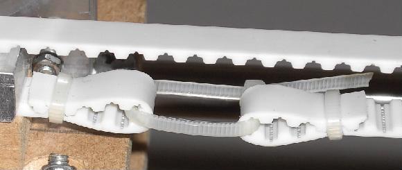
After installing the X-Axis, I found that it is quite important how far apart the two ends of the X axis are spaced, so my efforts to compensate for the supplied X belt being too short resulted in the holes for the smooth rods not lining up with the rods. I saw this picture on someones Facebook build album showing how he extended the belt using a cable tie. I'm not sure how he attached the tie to the belt, but will be attempting something like that to make my belt fit.
Photo of cable tie extended belt
- The MegaMendel page has a photo of the same extension using a cable tie. Here is a photo from that page:

Y Axis
Y Idler
Be warned that you probably need an additional washer against each bearing to allow the belt enough space for smooth running between the mudguard washers.


Y Motor
Be warned that you probably need an additional washer against each bearing to allow the belt enough space for smooth running between the mudguard washers.


Y 360 Bearing
The clearance for this part is small, so make sure you don't use a screw that is too long for the upper bearing in the picture.

Y 180 Bearing

Y Chassis
I have found this to be the trickiest bit to work out without instructions, so I have left it till last. Consequently, I have used all of the shorter M4 screws that come with the kit and don't seem to have the right screws left to do this job (All I have left are lots of the M4x40 screws that only have thread on the last half). I think you are supposed to use the M4x30 Phillips Pan head screws to mount the Y 360 Bearing and the Y 180 Bearing to the frog plate?
For some of the intermediate nylock nuts used in the this assembly, I drilled out the nylock plastic to be able to get them on the machine screw back end first.


More Pics (BlkTopTrvl)
This is how I origionally assembled the frog and y-bearings. THIS DID NOT WORK FOR ME.


After a lot of assembly and disassembly (over and over again) and reaching out for help, I was able to put this assembly together so that it works...


Instead of using the nuts back to back, this time, I used 1/2" nylon spacers.
Z Axis
Z Leadscrew Base (one with opto)
You will need 2 of these assemblies, only one of them has the opto mount.
| Name | Qty /w opto | Qty /wo opto | Type |
| Z Leadscrew Base | 1 | 1 | Laser Cut Part |
| Opto Spring | 1 | 0 | Laser Cut Part |
| Opto Holder | 1 | 0 | Laser Cut Part |
| Bearing | 2 | 2 | Hardware |
| M4x40 | 3 | 2 | Fastener |
| M4 Washer | 9 | 8 | Fastener |
| M4 Mudguard Washer | 4 | 4 | Fastener |
| M4 Nut | 3 | 2 | Fastener |

Be warned that you probably need an additional washer against each bearing to allow the belt enough space for smooth running between the mudguard washers.

Design Change
I could not find a screw long enough to attach the spring and opto holder so I emailed the TechZone and was told "The plywood functions as the nut. The 4x40mm bolt threads directly into it and it is tight. The previous version used a longer bolt , but would wobble. Which is very bad for proper operation of a opto endstop." --blktoptrvl

Z Motor


Z Tensioner
Be warned that you probably need an additional washer against each bearing to allow the belt enough space for smooth running between the mudguard washers.

Frame
Frame Sides

Left Side
BOM
| Name | Qty/assembly | Type |
| M8 Nut | 14 | Fastener |
| M8 Washer | 14 | Fastener |
| 370mm M8 Threaded Rod | 3 | Hardware |
| corner vertex | 3 | Laser Cut Part |
| Z Leadscrew base | 1 | Laser Cut Part |
| Z Motor Bracket | 1 | Laser Cut Part |


You will also need a measurement jig to get the distance between the corner vertices the same. I created a jig using one of the other bits if M8 rod, 4 nuts and 2 washers. I assembled the jig so that the outside of the two washers was 290mm apart. Then used it when tightening the nuts on the vertex pieces to ensure the spacing was right.

Right Side
BOM
| Name | Qty/assembly | Type |
| M8 Nut | 14 | Fastener |
| M8 Washer | 14 | Fastener |
| 370mm M8 Threaded Rod | 3 | Hardware |
| corner vertex | 3 | Laser Cut Part |
| Z Leadscrew base | 1 | Laser Cut Part |
| Z Tensioner Bracket | 1 | Laser Cut Part |


Assembled Frame
The pictures below show too many nuts on the front and rear bars. If you get the kit and do it this way, you will not have enough nuts. I was following the official Mendel build pics and it looks like they have too many nuts too (http://reprap.org/wiki/File:Frame-end-assembly.PNG).
Because the wood bites into the threaded rod really well, I didn't need to put any of the extra pairs of washers and nuts to keep the y axis in line (shown in the picture to the left and right of the Y-axis bearings and motor mount).
When putting this together I found that if I put the threaded rod in the chuck of my drill, I could put on 3 or 4 nuts on at a time.


Z-Screw Attachment at frame top
I spent quite a lot of time searching these photos looking to see how the z-screw is attached at the top of the frame. Unfortunately none of the pictures had a clear view of this assembly.
After searching some more, I found that there IS NO connection of the Z-Screw to the top of the frame, it sits free. -- blktoptrvl
Z Axis Installation
This is the same as the standard Mendel. Refer to the Mendel_frame#Installation_of_X-axis instructions.


Y Axis Installation
In order to get the Y Axis to sit properly with the Frog plate, be sure to get the orientation correct. The foot extensions for the plate should be up in the air. It took me a couple tries to get it right. Make sure you understand the orientation and to put the Y-Axis belt around the plate before tightening the second pair of mounts.
Left: How the belt is installed and tightened on. Center: Above view of the installed frog plate before other pieces are added. Right: the underside of the frog plate when installed.


This shows the Y bars installed before the screws and M8 nuts are tightened. You can also see the rubber feet that I have epoxied to the four base vertices (these do not come as part of the TechZone kit).

Mechanical Construction Issues
I have assembled the Y carriage and installed it, but it looks like there is very little room for the Y carriage print bed mounts to fit between the base vertex pieces. Is the Y carriage supposed to have the full range of movement? Or should it be stopped before it passes between the frame vertices? I went ahead and used a hacksaw to chop a couple of millimeters of each of the print bed supports.


Cutting Washers
The z-axis frame carriers(?) will not fit closely together as shown in these pictures because the supplied round washers interfere with each other. I searched locally for a cut (flat edge washer, then a square washer) but could find neither. I thought about getting a grinder and grinding down the round washers... in the end, I decided to use a pair of bolt cutters to slice a tangent off of the round washers. That was accurate and faster than grinding --bkltoptrvl

When trying to assemble some parts, I didn't have enough hands/fingers free to hold installed screws in place while trying to get other screws in. Instead of putting nuts on the ends of the screws temporarilly, I used small clamps to hold the already inserted screws in place. --blktoptrvl

Printbed problem
The Aluminium print bed sits (or is supposed to sit) in a routed recess in the laser cut printbed. Unfortunately, mine was too big for the routed recess. I needed to manually hack the routed recess with a stanley knife to make it large enough for the aluminium insert.


Once the bed is sitting flush in the recess, the width of the bed is still causing issues because it is partially obscuring the holes for mounting the bed to the Y Carriage. The kit creator suggests notching the printbed to allow room for the screws. The following pictures shows before and after the hole notching:

