Mendel Electronic Wiring
Contents
Introduction
This page describes how to wire up RepRap Version II "Mendel". Before you wire the machine up, test the circuit boards individually as described on this page.
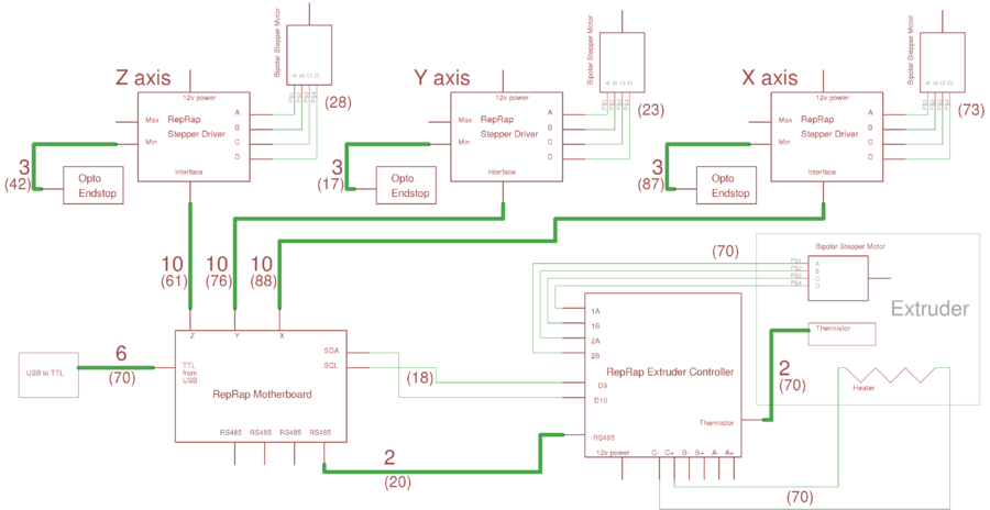
This is the overall Mendel wiring diagram; click the image for a full-resolution version. The wiring diagram is stored as an [Eagle] schematic in your download at mendel/electronice/mendel-wiring-diagram.sch. The latest version is in the [RepRap subversion repository here], but that may be an unstable version in development. In the diagram above multi-way connections are shown as thick lines with a number next to them. The number is the number of wires in the connection. Numbers in brackets are the lengths of the wires in centimeters. Thin wires are single wires.
One Mendel will need:
- A RepRap Motherboard,
- A Mendel USB and power connector,
- 3 RepRap Stepper drivers,
- 3 RepRap Opto Endstops, and
- As many RepRap extruder controllers as you have extruders.
For details on the individual printed circuit boards and how to build or adapt them, follow this link.
The power wiring is not shown on the diagram for clarity, but it is very simple. The 12 volts from the Mendel USB and power connector is connected in parallel to the three stepper driver boards and to all the extruder controller boards. The Motherboard does not need to be connected to Mendel's internal power connectors. It is powered by the USB connection from the computer.
The extruders are connected in parallel to the RS485 and to the SDA and SCL ports on the Motherboard. The system only has four connectors for these on the Motherboard, but you can chain these together up to any reasonable number (in theory it should be possible to drive 64 extruders at once...).
Wiring Video
The following video shows the runs of all the wires:
Power Cabling
Start by wiring up the 12-volt power cables. You'll need 1.1 m of twin wires.
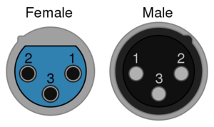
The standard RepRap 12v power connector is a 3-pin XLR connector.
The picture immediately above is looking into the socket (female) and at the pins (male). Pin 1 is the ground (negative) connection and pin 2 is +12v connection. Pin 3 is not used. Mendel has a panel-mounted male plug connector.
Use wires of different colours that are capable of taking 8 amps. If your wires are not twisted or paired you can easily twist them up yourself by putting one end of the pair in a vice, the other end in a hand twist-drill chuck, and winding. Do all the wire at once, then cut it.
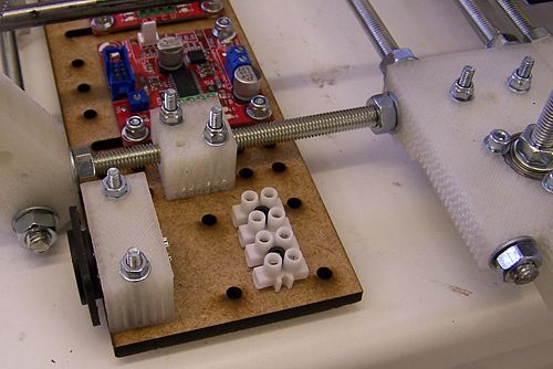
Attach a four-way "chocolate-block" connector beside the XLR power input. You may need to drill a couple of extra 3mm holes in the stepper-plate, depending on the hole-gaps in your connector.
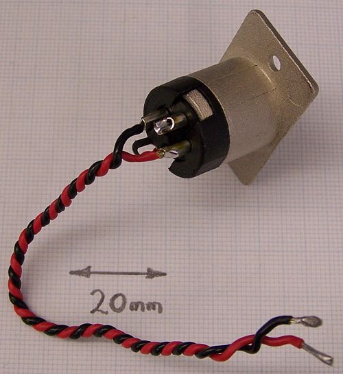
Solder two short wires to the XLR power connector as shown. Measure them to the two central connections in the chocolate-block. Then untwist them, put heatshrink on the terminals, and twist them up again. Make two small U-shaped pieces of wire to attach the two central chocolate-block connectors to the two outside ones. Put all the wires in the block, but don't tighten the screws yet.
Stepper Cabling
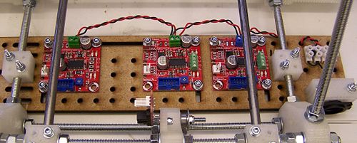
Chain the stepper driver boards' power connections together back to the chocolate-block.
Extruder Cabling
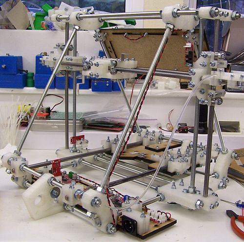
Run wires up the leg to the extruder board as shown.
Extruder stepper driver
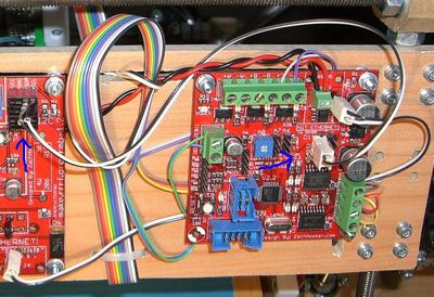
The extruder stepper is controlled by the extruder controller. But the motherboard talks directly to the stepper drivers on the extruder board, using the scl/sda pins on the motherboard and the d9/d10 connections on the extruder controller. The following image shows how the motherboard and extruder board are connected.
Finishing the power wiring and testing
Tighten all the screw connectors. Tug each wire with long-nosed pliers to make sure it is securely connected.
Use a continuity tester to make sure that:
- The power is getting to each board,
- The two power lines are not shorted, and
- The polarity on each board is correct.
Stepper wiring
When making up ribbon cables for the stepper control boards us 10-way insulation-displacement connectors (IDCs) on the ribbon cables. A pair of these should be the same way round. That is to say, when you put the cable flat on the bench, the projecting tabs on the IDC connectors that key with the sockets on the boards should both point the same way.
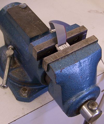
It is simple to put an IDC connector on a ribbon cable using an ordinary vice. You don't need a special tool. Push the cable through the connector so that it projects about 2 mm clear on the other side. Check that it is square and not at an angle. Push it together loosely by hand, then place it between the jaws of a vice. Tighten the vice gently to make the connection. Finally trim the 2mm projecting wires with a sharp blade making sure that you don't leave wire threads shorting.
The wires between the X stepper motor and its control board are quite long. You may need to solder extensions onto the steppper. Cut the stepper wires off at a length of about 50 mm, bare the ends, and put lengths of heat-shrink on them. Bare the ends of some 4-way ribbon cable and twist them onto the stepper wires. This will be neatest if you overlap them from opposing directions, though that will make twisting harder. Solder them, then put the heat-shrink on to insulate the connections.
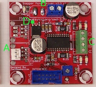
See here for help determining which stepper motor wires connect to A/B/C/D on the stepper driver board.
Optoswitch wiring
It is important to check the polarity of the opto-switch wiring. The connectors are marked GND, SIG and VCC. Using a meter check that the GND connection is connected to the 0v wire on the power chocolate block. The VCC connection should go to the 5-volt output of the 7805 regulator chip on the stepper controller board for the opto-switch. That is the pin by the letter D with the green dot in the picture.
The opto-switch plugs in at A. VCC is the pin at the top in this picture, the signal pin is in the middle, and GND is at the bottom.
USB wiring
The green (RTS) side of the USB<->TTL cable goes to the top of the Motherboard to the pin labeled GRN, and the black (GND) side goes to the bottom labeled BLK.
