TechZone Tip Assembly
The instructions on this page are for assembling the tip and extruder kit(s) from TechZoneCommunications.
The information may be useful for general assembly of tips and other designs, but no attempt is made to address them specifically in this document.
If you purchased a kit from TechZoneCommunications, and are having difficulty, please contact us (TechZoneCommunications) at Our Contact Page
Background
Here at TechZoneCom (short for TechZoneCommunications) we have learned the hard way, that the tip is probably the hardest and most finicky part in the RepRap. Unfortunately that set us up to cause a lot of problems for many of you (our customers and design users).
When we first released the LaserCut Mendel (LCMendel) we thought it would be a piece of cake to make and deliver hot ends, after all, everyone with a RepRap has a hot end and we presumed that they worked just fine. In the weeks (which became months) that followed we found out that we were Fools (notice I capitalized that word). We probably spent far too long re-inventing the wheel, and should have bitten the bullet and purchased everyone their favorite tip and called it good. That certainly would have saved us some money!
Even with the current version of tips that we have shipped, I am not completely content with the design, I am certain that there are some improvements to be made. However, what we currently provide (Aug 27, 2010) is a good design, and I am confident it is no more finicky or flawed than the many other designs out there. I did break down and order several in from other vendors and set them up and compared their performance before I finally released our tip.
With that in mind, you should know that tweaking the settings of your machine, will improve, or impare the performance of your printing - ALOT. I suppose that many of the more experienced RepRap users know this already, but, for those of you who are new to RepRap, this may be your first "warning."
Contents
Hot End Assembly

Included in the Kit
- (1) Brass tip; it is machined from a solid bar of brass and threaded to a standard 7mm thread, bored with ~3mm bore until it is about 1mm from the end, the end has a 1/2mm hole in it and is ground with a taper.
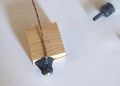
- (1) Oak Insulator, with Teflon insert; We played with several insulators, and didn't like any of them we even had trouble with the standard Teflon and/or peek insulators, then we found on a chart that Oak is 1/10th as conductive as the Teflon or peek! So, we make the insulator out of oak. We recommend some care in your firmware and tip construction, Wood is flammable....
- (1) Nichrome heater wire; This wire is insulated with fiberglass, but that fiberglass is just wrapped on the wire, so we overcoat that with high temperature silicone so that it doesn't unravel as you use it.
- (1) Type K thermocouple wire; This is insulated in a fiberglass braid, it has two wires in there, one wrapped in Yellow the other wrapped in red.
- (1) 1cc of High Temp Goop; we use two different kinds of "Goop" one is a high temperature silicone - which is copper colored - purchased from an auto parts store, the other is a silicone cement - which is black - purchased from a hardware store (both come in large qty packages, so we repackage it into a small syringe).
- (2) small brass or copper crimp connectors (these are shipped to you in a small envelope)
- (2) Small screws to attach the Oak block to the extruder body
Hot End Assembly Instructions
Before we start the assembly, I strongly recommend that you test the thermocouple to make sure it has a low resistance, it should be well under 6 ohms. You test it by putting the red and yellow leads onto the ends of your multimeter and seeing what it shows. It should basically look like a short. I recommend this, because there is nothing worse than putting your whole end together and then finding out that the thermocouple was made poorly; Then you have to tear your tip apart and do it all again.
Note (--crazytiti 17:45, 25 November 2011UTC): I get a thermocouple with both ends similar and after stripping one end I get "infinite" on my multimeter.Back to basis that a thermocouple is juste two wire of different metal connected together at one end I strip the other end and connect the two wire together. Now my thermocouple is working.


Note: It may be easier to scrap, crimp, and solder the ends of the nichrome wire to leads, before wrapping and adding goop. It may save you a lot of headache later if you realize now and think about the processing you will need to do to the tips of the nichrome wire. Read ahead a couple of paragraphs and decide if you are going to solder/crimp before or after fixing it to the brass.


Note (--DeuxVis 11:21, 12 July 2011 (UTC)DeuxVis): Make sure the "naked" end of the thermocouple - were the two wires are joined - is not touching neither the nichrome wire or the brass tip. Otherwise you may end up with a short between the thermocouple and the nichrome, and this could burn your thermocouple. Use a tiny piece of kapton tape or place some cement between the brass tip and the thermocouple end, and make sure the two wraps of nichrome which attach the thermocouple are not touching that insulation-free end.

- One is a hight temperature silicone we purchase from an autoparts store, it is good up to ~350 degrees Celcius. It also remains flexible after it cures - give it about 24 hour to cure. it can be handled and you can finish the assembly after about one hour. It is copper colored.
- The other is a Silicone Cement product we get at a hardware store. It is good up to ~535 degrees Celsius. It is Hard and rigid when it cures, I would give it 24 hours of cure time as well. It can be handled after about 2 hours. It is black in color.
Both of these are shipped to you in a small syringe, you can use the syringe to apply the goop to the tip, I find it is helpful to use a toothpick to help press it into place and spread it around the way I want it. Sometimes, it will get stuck in the small end of the syringe (especially the black stuff, it has chunks and fibers and stuff in it) I just use a toothpick to clear the end of the syringe (picture in gallery below) If you don't like the syringe, you can just cut it apart, we use the syringe for ease of packaging and shipping (and to keep it from curing before you get to use it).
One cc is more than enough to do your tip, you can save the extra for a second tip, or you can apply the extra to your tip to act as a better insulator as I have done (see gallery below for photo).
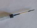
Using a toothpick to clear the tip when it gets stuck.
All the cement from the syringe applied as extra "insulation."

Let your tip dry and cure for an hour or two before continuing. Go watch a movie, or take your sweetheart to dinner (it may help make up for the long hours you have spent on this project!)


All this effort is made, because the nichrome wire does not solder well, in fact it solders very very poorly.
Thermocouple A-D converter with OneWire

You may already have a Thermocouple A-D (of a different type) Information about it can be found here
Included in the Thermocouple Add On
- (1) Thermocouple A-D converter with OneWire
- (1) Cat 5 cable with one RJ45 connector
- (1) 3 pin connector
- (1) Small mounting screw
- (1) --If ordered separate from the tip kit-- Thermocouple wire (not shown in photo)
Connection Instructions (Pinouts)
(If you have an updated kit, you don't need to worry about this. It should have Rj45 to RJ45 from the tip manager to the board.)


Our wires happen to be in the following order:
- Striped Orange
- Solid Orange
- Striped Green
- Solid Green
- Striped Blue
- Solid Blue
- Striped Brown
- Solid Brown
If your wire colors are in a different order, then just substitute your color order for mine. Like if Solid Green-#4 and striped blue#5 are reversed, then every time I say Solid green you would use the striped blue and every time I say Striped Blue, you would use solid green.


I use a small screw driver to press them into the connections. I STRONGLY recommend using a multimeter to test the connection when you are done.


Firmware Files
You will need to install firware from this zip file for this A-D to work.
This firmware is for the RepRap Host software and probably won't work with Makerbot's Replicatorg software (you are welcome to try and let me know). Kurt (the programmer for TechZoneCommunications) has created this great page, which explains all the software changes we have made to the firmware. There is also a schematic for the adapter on that page.
Connection to the Extruder Body
The oak block connects to the bottom of the extruder body using the two screws provided. The screws are normally installed at a slight angle. Drill a pilot hole for the screws to follow (it is mighty tough to drive a screw into oak without a pilot hole). Be careful not to put the screw into the Teflon sleeve.
The A-D converter can be mounted anywhere on the extruder body, I try to mount it a little further away from the motor, but that isn't required. There is a single mounting hole and a small screw provided for this purpose.