RepRapPro Huxley improvements
|
English • العربية • български • català • čeština • Deutsch • Ελληνικά • español • فارسی • français • hrvatski • magyar • italiano • română • 日本語 • 한국어 • lietuvių • Nederlands • norsk • polski • português • русский • Türkçe • українська • 中文(中国大陆) • 中文(台灣) • עברית • azərbaycanca • |
Introduction | Frame assembly | Y axis assembly | X axis assembly | Z axis assembly | Heated bed assembly | Extruder drive assembly | Hot end assembly | Wiring | Commissioning | Printing | Maintenance | Troubleshooting | Improvements
| A notice about these instructions! |
|
These instructions are open to editing by everyone and anyone. |
This is the place to describe improvements to RepRapPro Huxley
Using the bed for Z homing and bed level compensation
The Huxley already has the functionality to probe the bed built-in to the heated bed. Build the bed as follows:
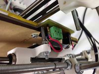
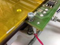
- Solder a short wire into each of the three points next to the three mounting screws (first image below - shows soldered pins, with crimp on wire).
- Connect other end of each wire to the mounting screw, or spring.
- Contact is made/broken by the head of the screw (second image below).
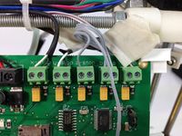
- Connect the 4th wire of the heated bed cable to the LEFT-hand contact of Z endstop (third image below).
- Test by hand first. Send M119 to sense the state of the endstops, then push down on the bed and send M119. The state of the z endstop should change. The thermistor, bed activation and z-probe wire all share the same ground, through the bed thermistor ground wire, which is the right-hand side screw terminal on the Melzi.
Notes on using the bed probing:
- In long term use the probing may not be 100% reliable, as the contact surfaces can get oxidised over time; keep the contact points between the mounting screws and heated bed PCB clean.
- It will work better if the nozzle is clean when probing.
- For Z homing, move the probe to the centre of the bed before homing Z. You can add this to the start.gcode of your slicing profile:
G28 X0 Y0 ; homes X and Y
G1 X75 Y75 ; centres X and Y
G28 Z0 ; homes Z
Bed compensation should also work, though untested (please add instructions below). You will have to use the main branch version of Marlin to do this, which should be able to do it, as the code has not been added to the RepRapPro version of Marlin.
Huxley Mini-Spool
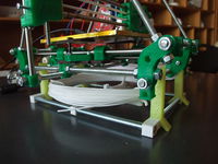
A horizontal mini-spool to store a small amount of filament right under your Huxley.
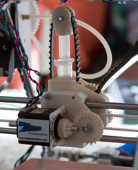
Mattroberts' Huxley Paste Extruder
Replace the hotend with a 5ml syringe.
Mattroberts' Huxley Carriage
Adds nuttraps to the carriage, so you replace the self tapping screws with metal screws.
Achieving Finer Quality Prints
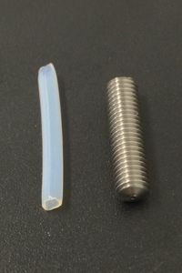
Upgrading the standard 0.5mm nozzle which comes with your Huxley kit to the RepRapPro 0.3mm nozzle will produce finer quality prints at 100 microns or better.
(See: eMAKERshop, 0.3mm Stainless Steel One Piece Nozzle)
- N.B: A feeler gauge is required to accurately calibrate the nozzle/bed, also print time is substantially increased!
PLA vs. Aluminium Pulleys
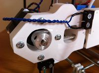
Upgrading the X & Y axis printed PLA pulleys with T2.5-16T aluminium replacements can increase print accuracy, especially when printing circular or curved objects. This will only be true if the metal pulley's bore is more concentric to it's teeth than on the PLA pulley.
The pulley illustrated is "Aluminium with Zinc plated Steel Flanges. They are factory-drilled and reamed to 5mm +0 -0.02mm to match the standard shaft diameter for NEMA17 or NEMA14 motors used in most RepRaps, and factory-drilled and tapped for M4 x 6mm grubscrews" (See: eMAKERshop, Think3DPrint3D).
You will have to remove the steel flange at one end of both pulleys (using a metalwork lathe) in order to mount them on the Huxley's drive shafts.
- N.B: Don't forget to reconfigure the firmware's steps/mm setting.
Smooth Rod Lubrication
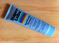
Optimum carriage travel for all 3 axis can be obtained by applying "Super Lube" (Synthetic Grease with PTFE) to all smooth rods.
It provides a substantial improvement over white lithium grease, as it provides the lowest coefficient of friction.
- N.B: It's costly for a relatively small quantity.
DIY Cooling Rack
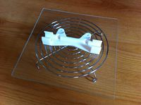
You can make a small wire (glass bed) cooling rack by obtaining a 120mm diameter PC fan guard.
Folding down all four circular lugs creates small support legs.
