RAMPS/fr
|
English • العربية • български • català • čeština • Deutsch • Ελληνικά • español • فارسی • français • hrvatski • magyar • italiano • română • 日本語 • 한국어 • lietuvių • Nederlands • norsk • polski • português • русский • Türkçe • українська • 中文(中国大陆) • 中文(台灣) • עברית • azərbaycanca • |
Release status: Working

| Description | Electronique modulaire RepRap, basé sur l'Arduino MEGA.
|
| License | |
| Author | |
| Contributors | |
| Based-on | |
| Categories | |
| CAD Models | |
| External Link |
Note du traducteur (NDT):
- En cours de traduction, la version originale reste la seule référence à jour sur le sujet.
- Dernière traduction le 29/08/2013
Contents
Introduction
RepRap Arduino Mega Pololu Shield, ou RAMPS pour faire court. Elle est conçue pour fournir toute l'électronique nécessaire au fonctionnement d'une RepRap avec un faible encombrement et un prix bas. La RAMPS s'interface sur la carte la plus puissante disponible chez Arduino (NDT : proposition à confirmer), l'arduino MEGA, qui dispose de nombreux emplacements d'extension. Le module embarque le driver pas à pas et le controlleur de l'extrudeur sur un Arduino MEGA "shield" pour faciliter la maintenance, le remplacement de composants, la possibilité d'upgrade et d'ajouts de nouvelles fonctions. De plus, plusieurs extensions Arduino peuvent être ajoutées du moment que le module principal RAMPS reste le module principal et soit placé "en haut" (NDT : hiérarchiquement) des autres.
La version 1.4 est constituée de condensateurs et résistances montés en surface (CMS ou SMD en anglais) afin de faciliter la mise en place d'un couvercle ou son intégration dans une boîte. Tout comme la version 1.3 afin de contenir plus de choses, la RAMPS n'est plus conçue pour être facilement gravée à la maison. Si vous voulez graver votre propre carte choisissez plutôt la version 1.25 ou la Carte Generation 7. En effet, les versions 1.25 et précédentes sont des cartes dessinées en "1,5 couches" (c'est à dire que c'est une carte double face dont un côté peut facilement être remplacée en soudant des fils souples) que l'on peut graver sur une RepRap ou imprimer par la méthode classique de transfert par toner.
Cette carte est majoritairement basée sur le projet Electronique Pololu d'Adrian et le travail effectué par Tonok. Copper etch resists methods suggested by Vik. Également inspiré par le travail de Vik avec EasyDrivers. La conception du circuit est principalement basée sur le modèle Electronique Pololu d'Adrian. Joaz de RepRapSource.com a fourni la définition initiale des broches et de nombreuses améliorations de conception. Ainsi l’inspiration, les suggestions et les idées de Prusajr, Kliment, Maxbots, Rick, et beaucoup d'autres dans la communauté RepRap.
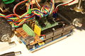
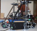
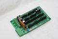
Mendel printed RAMPS wired to Mendel.
Mendel avec RAMPS monté en boitier.
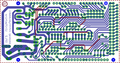
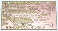
screen capture of 2-sided RAMPS layout
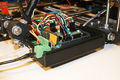
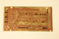
commercially fabbed 2-sided RAMPS wired to Mendel
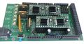
RAMPS1.3


Fonctionnalités
- Elle a des dispositions pour les robots logiques et les extrudeuses.
- Extension pour contrôler d'autres accessoires.
- 3 sorties MOSFET pour résitance chauffante / ventilateur et 3 entrées pour thermistance.
- Protégée par un fusible de 5A pour plus une sécurité et une protection des composants accrues.
- Contrôle du plateau de chauffe avec un fusible supplémentaire de 11A
- 5 supports de carte Pololu stepper driver board
- Pololu boards are on pin header sockets so they can be replaced easily or removed for use in future designs.
- Broches I2C et SPI disponible pour de future extansion.
- Tous les MOSFET sont raccordé à des broches PWM pour plus de polyvalence. (attention : pas de diode de roue libre en cas de charge inductive)
- Les connecteurs de type servo sont utilisées pour connecter les fin de courses, les moteurs, et les LED. Ces connecteur sont plaqués or, 3A RMS, très compacts, et disponibles au mondialement.
- Ajout de lecteur de Carte SD disponible -- Disponible, réalisé par Kliment - Sdramps
- LED d'indication d'allumage du chauffage.
- Possibilité de connecter 2 moteurs sur l'axe Z pour la Prusa Mendel
<videoflash type="youtube">0k_KArg_sgA</videoflash>
Conseils de sécurité

|
Une fois que vous commencer à alimenter en électricité votre RepRap - même avec seulement 12 volts - vous devez prendre des précautions de base pour éviter les incendies. Juste au cas où ceux-ci échouent, testez votre système de sécurité : Détecteur de fumé. Vous n'en avez pas ? Obtenez un ! |
Support
The primary channel for RAMPS support is the RAMPS Forum
Réalisation et Utilisation
Voir la page correspondant à la version que vous réalisé RAMPS1.4, RAMPS1.3 or RAMPS 1.2
Composition
Schémas
Liste des Schémas :
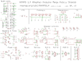
Schéma générale de la carte

Source
| FILE ID# | Type | Déscription | téléchargement |
|---|---|---|---|
| File:ArduinoMegaPololuShield.zip | Eagle Files | These are the files you need to make the board.(Use the File: link to the left to access older versions of the file.) | media:ArduinoMegaPololuShield.zip |
| File:RepRapjr.lbr | Eagle Libraries | The components used in this board are here. see Eagle_Library | media:RepRapjr.lbr |
Versions Personnalisées
Grogyans
Will have locking connectors for the motors. Uses the MAX6675 thermocouple sensor, which essentially replaces the AD595. Less vias, which should also increase building time. Bottom only, to enable the possibility of a RepRap or toner transfer method to fabricate the board. Moved the power LED to the front for easy identification. Providing the user has a proto-shield for Mega, there is plenty of pins left for them to play with. By using another tiered board, will alow the possibility of more extruders and LCD all of which can communicate over the I2C protocol.
Showcase
printed on a RepRap Mendel with the etch resist method Using_cad.py
attempt at printing labels with sharpie
Two-sided PCB Built v1.0
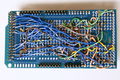
messy back of the first prototype of RAMPS -- built on a generic megaproto shield with point to point wiring, rather than a custom RAMPS PCB
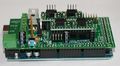
RAMPS with standard pin headers


Change Log
- 1.4 August 4, 2011
- Changed capacitors and resistors to surface mount components
- Added LEDs to mosfet outputs
- Added bulk capacitors for each stepper driver
- Added pull up resistors to enable to override the Pololu drivers default enabled state
- Added mosfet gate resistors
- Added pull-ups for I2C
- Servo1 connector moved to pin 11 to free 7 for ADK
- Fixed thermals
- Servo 5V supply is only connected to VCC if a jumper is added
- Reset switch changed for small footprint
- Moved Aux conectors around a bit and increased board size ~0.1"
- Added some space around Q3 for a small heatsink
- 1.3 May 13, 2011
- Added 5th stepper driver socket
- Added 3rd thermistor circuit
- Added Heated bed circuit w/ 11A PTC fuse, changed to 4 position pluggable input jack to accommodate additional current
- Increased board size to 4"x2.32"
- Pin order on heater outputs changed
- Increased spacing increased to accommodate different connectors
- Added connectors for optional 2 motors on Z driver
- Added connector for PS control
- Improved expansion connector layout
- Moved LED towards corner and added resistor to LED circuit
- No longer optimised for home etching :(
- License changed to GPL v3 or newer
- v1.2 January 04, 2011
- Added 0.1" motor connector to RAMPS for each driver (motors no longer have to be connected on top of stepper drivers)
- Added breakouts for serial and I2C
- Changed extra power and pin headers around for easier connection to extra boards.
- Lost most extra analog breakouts
- More silk screen and bottom layer fixing
- v1.1 September 30, 2010
- Replaced power barrel jack with plug-able screw terminal
- Added jumpers to select micro-stepping on stepper driver boards
- Added debug LED
- Changed mosfet pins to be compatible with FiveD firmware
- Reduced number of 100uF capacitors to 1
- Added 100nF capacitor to 12V input
- Put auxiliary 12VIN and GNDIN pads in a straight line
- Silk screen and bottom layer cleaned up
- v1.0 Original RAMPS PCB design
- v0.1? Point to point wired Arduino MEGA Prototype shield
Comment l'obtenir
Le PCB et les composents sont disponible chez :
- Ultimachine
- Brupje - see items for sale
- ReprapSource
- German RepRap Foundation (GRRF) - seller of Ramps electronics, plastruder parts, stepper motors, plastics (ABS), mechanics kits.
- XYZ-Printers
- Reprapworld.com
- RepRapDiscount.com
La Carte complètement assemblé est disponible chez :
- Charlie's 3D Technologies Fully assembled RAMPS 1.4
- GADGETS3D.com Fully assembled RAMPS 1.4
- Fabster3D Ebay
- Ultimachine
- Brupje - see items for sale
- XYZ-Printers
- MixShop RAMPS 1.4 Pre-Assembled
- A2APrinter RAMPS 1.4 Pre-Assembled
- BCNdynamics store
- 2PrintBeta
- Reprapworld.com
- RepRapDiscount.com Fully assembled RAMPS 1.4 including wiring kit (20 cables)
- Create3D RAMPS 1.4 Pre-Assembled
- eMotion Tech RAMPS 1.4 Assembled
- FunRepRap RAMPS 1.4 Assembled
Liste de suggestion
This shield would like to replicate with the following external boards
- Additional Stepper Driver.
- Replace the resettable fuse with a traditional 15A blade fuse and holder?
- DC Driver
- Two additional Thermistors (for a second extruder and heated chamber)
- Include a second resistor in parallel to the thermistor to reduce self heating. See here
- Thermocouple
- Carte SD -- Disponible, réalisé par Kliment - Sdramps
- Ecran de controle LCD
- Connection Ethernet
- Host USB
Dépannage
- Check List
- RAMPS shield firmly seated on Arduino MEGA
- No stray wires/metal to cause short
- All connections firmly seated, screws tight
- Power connection oriented correctly, connected to RAMPS shield (only USB is connected to MEGA)
- Thermistor connected to T0
- Firmware uploaded
- Stepper driver potentiometers to a sane setting (maybe 25% from CCW to start, adjust to enough power to drive axis + not overheat)
- Heater wires properly connected
- Cannot connect?
- Verify firmware and host software baud rate matches
- Disconnect USB, reconnect, and retry
- It may be a problem with the software you're using (repsnapper). Try using pronterface.
- Stepper motor getting too hot?
- Adjust the potentiometer (small screw) on the stepper driver in question by rotating the screw counterclockwise to decrease the current going to the stepper motor.
- My fan is not working.
- If you have RAMPs 1.3+ and sprinter firmware (set with the default pins for RAMPs 1.3), try attaching the fan to D9 output.
- In pronterface, the fan can be turned on by using the M106 command and turned off with M107.
Stepper Driver Testing
If you are not sure whether you have a problem with your RAMPS or the stepper drivers you can test that the driver is getting the power and signals it needs to work.
- Stepper motors getting too hot?
- Adjust the potentiometer (small screw) on the stepper driver by rotating the screw counterclockwise to decrease the current going to the stepper motor.
Use a meter of some sort to test the signals at one of the motor drivers. Be careful not to short anything out. You can use a (-) pad in AUX-1 for ground and test the voltage on VMOT, VDD, EN, STEP, and DIR. If all of these are working correctly then the stepper driver is likely bad.
                    High(5V) when disabled, Low when enabled  EN-|     |-VMOT  12V (or voltage at 5A side of input power connector
                                              Set by Jumper  MS1-|     |-GND 0V
                                              Set by Jumper  MS2-|     |-1A     ---------------| <Motor Coil A
                                              Set by Jumper  MS3-|     |-2A     ---------------|____
                                     Not used (tied to SLP)  RST-|     |-1B      -----------------/  |  <Motor Coil B
                                     Not used (tied to RST)  SLP-|     |-2B      -------------------/
                                  Pulse High for each step  STEP-|     |-VDD  5V
Switches between High and Low when driven direction changes  DIR-|     |-GND 0V
Question & Réponse
- What power supply you recommend for your ramps board. I have just finished assembly and looking at the diagrams for a pc power supply and wondering about the separate amperages for the extruder and heated bed. Can they be higher amps without damage?
Yes, the power supply being capable of more amps than required is the desired configuration. The current shown are the max supported by RAMPS and is the minimum the power supply should be capable of. It is also OK to have both of the inputs on RAMPS connected to one PSU with enough capacity. If you are not using a heated bed the entire thing can run off the 5A side (D8 will just not work).
- I got a RAMPS V1.3 as part of a kit, but it doesn't have any installation instructions - just a schematic. Can you point us to a good tutorial for connecting everything? (i.e. stepper motors, opto flag pcb's, power, data, etc) Some of it (like the single USB port) is obvious, but some of it isn't.
See RAMPS1.3 for instructions for version 1.3. There is a version navigation bar at the top of the RAMPS pages that allow you to jump to a specific versions instructions. There is a very helpful graphic under Final Check section.
- For RAMPS V1.3 the power section of the schematic shows several places with GND/12V (C4/C6, X4-2/1, X4-4/3, VCC/D12). Which one is the GND/12V from the power supply? Is it the round power plug like a laptop power plug? Also, is the outside of that plug GND while the inside is +12V? My kit came with a note warning not to reverse the input power or it would cook the board . . . and a plug adapter with no labels that can be installed either way.
See the connecting power section of your version's page. The round plug is on the Arduino MEGA and will only power the MEGA. You need to power the green pluggable connector, it should not be reversible and the board should be marked (+) and (-). If for some reason your board is not marked you can follow the diagrams and pictures in the wiki.