Arduino Mega Pololu Shield/zh cn
|
English • العربية • български • català • čeština • Deutsch • Ελληνικά • español • فارسی • français • hrvatski • magyar • italiano • română • 日本語 • 한국어 • lietuvių • Nederlands • norsk • polski • português • русский • Türkçe • українська • 中文(中国大陆) • 中文(台灣) • עברית • azərbaycanca • |
Release status: Working

| Description | Arduino based modular RepRap electronics.
|
| License | |
| Author | |
| Contributors | |
| Based-on | |
| Categories | |
| CAD Models | |
| External Link |
RepRap Arduino Mega Pololu Shield 或者简短的称作“RAMPS”,它被设计成在一块电路板上容纳reprap所需的所有电子器件,而且价格低廉。借助强大的Arduino MEGA平台,RAMPS和Arduino MEGA芯片相互作用,并且有足够的扩展空间。Arduino MEGA shield上采用模块化设计,拥有步进电机的插头和挤出机控制元件的插头,易于维修、组建更换、升级功能和扩展。 此外,一些arduino 扩展板能够被添加到系统上,只要主RAMPS板能够被保持在堆栈的最上层。
Contents
简介
Version 1.4使用表面安装电容和电阻来进一步解决边缘覆盖问题。自version 1.3起,为了安装更多的材料,RAMPS不再为简易电路家庭蚀刻进行设计。如果你想蚀刻你自己的印刷电路板,要么使用version 1.25 ,要么使用 Generation 7 Electronics。Version 1.25或者更早期的版本采用“1.5层设计”(i.e,他是双面板,但是其中一层很容易被电线跳线取代),它的电路板能用reprap打印机打印,通过蚀刻抗腐蚀笔的方法,或者通过家庭快速调色剂传输的方法。
这块板主要是基于 Adrian's Pololu_Electronics,通过Tonok工作。铜刻蚀抵抗方法由Vik建议。同样受启发于vik的 EasyDrivers的工作。电路设计主要基于Adrian's Pololu_Electronics。RepRapSource.com的Joaz 提供初始针设计和许多改进。很多灵感、建议和创意来自Prusajr, Kliment, Maxbots, Rick和reprap社区的很多人。
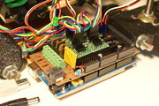
Mendel printed RAMPS wired to Mendel.
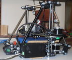
Mendel with RAMPS in enclosure mounted.
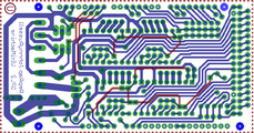
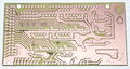
screen capture of 2-sided RAMPS layout
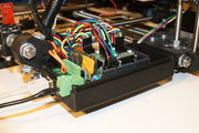
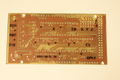
commercially fabbed 2-sided RAMPS wired to Mendel


特点
- 它有cartesian机器人和挤出机的规则。
- 可扩展去控制其他配件。
- 为加热器/风扇输出提供三个场效应管和三个热敏电阻电路。
- 5A保险丝为了附件安全和组件保护。
- 额外的11A保险丝控制热床
- 安装5个Pololu步进驱动板
- Pololu板是在针头插座上,所以它们能被很轻易的移动,或者为以后使用而移除。
- I2C and SPI为未来扩展使用
- 为了多功能,所有的场效应管钩住pwm针脚。
- 伺服模式连接器被使用以连接停止器、电机和二极管。那些连接器是镀金的,额定3A,非常紧凑,并且全局可见。
- B型号usb插座
- 可用sd卡附加,由Kliment制造。
- 加热器输出开启时led指示
- 为Prusa Mende设计,连接2个电机到Z的选项。
<videoflash type="youtube">0k_KArg_sgA</videoflash>
电压和电流注意事项
标准的RAMPS有5A可更换保险丝运行arduino mega、步进电机驱动器、d9和d10输出。保险丝额定最高电压30v,而其他只额定最低电压,所以在使用大于12v的电压时要小心。 标准RAMPS有额定11v的保险丝运行d8输出,这个保险丝额定最大16v。 时刻记住,RAMPS被开发在12v系统里,但是如果有各种保护措施,它也能运行在24v系统里。在没有修改的情况下,大多数RAMPS可以很愉快的运行在13.8v或者稍高。在标准设置下,不建议超过15v,尤其是你从低成本供应商那里买的板,它可能使用低规格组件。 注意:
- 一些变种RAMPS板使用真正的保险丝代替ptc保险丝(比如GRRF RAMPS),最大的电流限制当然会不同。
- 很多psu(电源设备)高估它们的最大电流容量,你需要的最大电流将依靠你自己的组件和它们上面的电压。标准的RAMPS板,运行有热床的机器,你的psu电源装置应该产生12v电压和大于16a的电流。(20a最好,但是有些电源高估它们的能力)
安全贴士

|
一旦你开始在你的reprap上放入电子器件,即使只是12v电压,你也应该采取基础常识性的预防措施以避免火灾。
只是万一失败了,检查一下你的车间smoke detector,没有烟雾检测?买一个! |
支持
RAMPS支持的最基本的通道是 RAMPS Forum
建造和使用
请看你正在建造的版本的对应网页RAMPS1.4,RAMPS1.3 or RAMPS 1.2
材料
原理图
下面是最近的原理图,要看老版本请点击图片,再次点击看全图。

来源
| FILE ID# | TYPE | DESCRIPTION | DOWNLOAD |
|---|---|---|---|
| File:ArduinoMegaPololuShield.zip | Eagle Files | 这里是你制造板所需的文件。(Use the File: link to the left to access older versions of the file.) | media:ArduinoMegaPololuShield.zip |
| File:RepRapjr.lbr | Eagle Libraries | 这块板所需的组件在这。 see Eagle_Library | media:RepRapjr.lbr |
自定义版本
Grogyans
将有电机的锁定连接器。 使用MAX6675热电偶,代替了AD595。 更少的通孔,也应该能减少建造时间。 仅在底部安装,使使用reprap或者色粉转移方法建造板子成为可能。 电源灯被移动到前部,更容易识别。 在使用者有一个mega原型机的前提下,留给他们足够的针脚去玩。 通过使用另一个分层板,允许更多的挤出机或者液晶屏幕,它们之间通过I2C协议通讯。
陈列柜
printed on a RepRap Mendel with the etch resist method Using_cad.py
attempt at printing labels with sharpie
Two-sided PCB Built v1.0
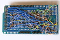
messy back of the first prototype of RAMPS -- built on a generic megaproto shield with point to point wiring, rather than a custom RAMPS PCB
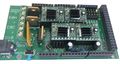
RAMPS with standard pin headers


改变日志
- 1.4 August 4, 2011
- Changed capacitors and resistors to surface mount components
- Added LEDs to mosfet outputs
- Added bulk capacitors for each stepper driver
- Added pull up resistors to enable to override the Pololu drivers default enabled state
- Added mosfet gate resistors
- Added pull-ups for I2C
- Servo1 connector moved to pin 11 to free 7 for ADK
- Fixed thermals
- Servo 5V supply is only connected to VCC if a jumper is added
- Reset switch changed for small footprint
- Moved Aux conectors around a bit and increased board size ~0.1"
- Added some space around Q3 for a small heatsink
- 1.3 May 13, 2011
- Added 5th stepper driver socket
- Added 3rd thermistor circuit
- Added Heated bed circuit w/ 11A PTC fuse, changed to 4 position pluggable input jack to accommodate additional current
- Increased board size to 4"x2.32"
- Pin order on heater outputs changed
- Increased spacing increased to accommodate different connectors
- Added connectors for optional 2 motors on Z driver
- Added connector for PS control
- Improved expansion connector layout
- Moved LED towards corner and added resistor to LED circuit
- No longer optimised for home etching :(
- License changed to GPL v3 or newer
- v1.2 January 04, 2011
- Added 0.1" motor connector to RAMPS for each driver (motors no longer have to be connected on top of stepper drivers)
- Added breakouts for serial and I2C
- Changed extra power and pin headers around for easier connection to extra boards.
- Lost most extra analog breakouts
- More silk screen and bottom layer fixing
- v1.1 September 30, 2010
- Replaced power barrel jack with plug-able screw terminal
- Added jumpers to select micro-stepping on stepper driver boards
- Added debug LED
- Changed mosfet pins to be compatible with FiveD firmware
- Reduced number of 100uF capacitors to 1
- Added 100nF capacitor to 12V input
- Put auxiliary 12VIN and GNDIN pads in a straight line
- Silk screen and bottom layer cleaned up
- v1.0 Original RAMPS PCB design
- v0.1? Point to point wired Arduino MEGA Prototype shield
在哪里得到它
空的pcb板和组件由下获得
- 为了便于维护,在不久的将来,这部分将要和reprap购买者指南合并buyers guide,所有未来网店附件都会搬到那。
- Think3dPrint3d
- Ultimachine
- ReprapSource
- XYZ-Printers
- Reprapworld
- RepRapDiscount
- NorcalReprap.com
- Makemendel
- opensourcehardware
完全组装板由下获得
- Ultimachine RAMPS Original Developer
- Austrian Reprap
- Aus3D
- eMotion Tech
- RobotDigg
- RepRap Z eBay
- Charlie's 3D Technologies
- GADGETS3D.com
- Fabster3D Ebay
- SainSmart
- MakerFarm
- electronic things GmbH
- Brupje
- XYZ-Printers
- MixShop
- A2APrinter
- BCNdynamics store
- Moebyus Machines
- Kitprinter3D
- Impresoras3DLowCost
- 2PrintBeta
- Reprapworld
- RepRapDiscount
- Create3D
- SeeMeCNC
- UltiBots
- NorcalReprap
- RepRap.me
- 3D Printer Czar
- Prototyp3d
- Replicator Warehouse
- DIY-India.com
- Cubic-Print
- PrototypeShop
- Thingibox
- Makemendel
- Opensourcehardware
- StaticBoards
- NIOZ (Ru)
希望列表
这个shield板想要复制下面的外置板
- Additional Stepper Driver.
- Replace the resettable fuse with a traditional 15A blade fuse and holder?
- DC Driver
- Two additional Thermistors (for a second extruder and heated chamber)
- Include a second resistor in parallel to the thermistor to reduce self heating. See here
- Thermocouple
- SD Card -- Available now made by Kliment - Sdramps
- Control Panel w/LCD
- Ethernet
- Host USB
排错
- Check List
- RAMPS shield firmly seated on Arduino MEGA
- No stray wires/metal to cause short
- All connections firmly seated, screws tight
- Power connection oriented correctly, connected to RAMPS shield (only USB is connected to MEGA)
- Thermistor connected to T0
- Firmware uploaded
- Stepper driver potentiometers to a sane setting (maybe 25% from CCW to start, adjust to enough power to drive axis + not overheat)
- Heater wires properly connected
- Cannot connect?
- Verify firmware and host software baud rate matches
- Disconnect USB, reconnect, and retry
- It may be a problem with the software you're using (repsnapper). Try using pronterface.
- Stepper motor getting too hot?
- Adjust the potentiometer (small screw) on the stepper driver in question by rotating the screw counterclockwise to decrease the current going to the stepper motor.
- My fan is not working.
- If you have RAMPs 1.3+ and sprinter firmware (set with the default pins for RAMPs 1.3), try attaching the fan to D9 output.
- In pronterface, the fan can be turned on by using the M106 command and turned off with M107.
步进驱动器测试
If you are not sure whether you have a problem with your RAMPS or the stepper drivers you can test that the driver is getting the power and signals it needs to work.
- Stepper motors getting too hot?
- Adjust the potentiometer (small screw) on the stepper driver by rotating the screw counterclockwise to decrease the current going to the stepper motor.
Use a meter of some sort to test the signals at one of the motor drivers. Be careful not to short anything out. You can use a (-) pad in AUX-1 for ground and test the voltage on VMOT, VDD, EN, STEP, and DIR. If all of these are working correctly then the stepper driver is likely bad.
                    High(5V) when disabled, Low when enabled  EN-|     |-VMOT  12V (or voltage at 5A side of input power connector
                                              Set by Jumper  MS1-|     |-GND 0V
                                              Set by Jumper  MS2-|     |-1A     ---------------| <Motor Coil A
                                              Set by Jumper  MS3-|     |-2A     ---------------|____
                                     Not used (tied to SLP)  RST-|     |-1B      -----------------/  |  <Motor Coil B
                                     Not used (tied to RST)  SLP-|     |-2B      -------------------/
                                  Pulse High for each step  STEP-|     |-VDD  5V
Switches between High and Low when driven direction changes  DIR-|     |-GND 0V
问与答
- What power supply you recommend for your ramps board. I have just finished assembly and looking at the diagrams for a pc power supply and wondering about the separate amperages for the extruder and heated bed. Can they be higher amps without damage?
Yes, the power supply being capable of more amps than required is the desired configuration. The current shown are the max supported by RAMPS and is the minimum the power supply should be capable of. It is also OK to have both of the inputs on RAMPS connected to one PSU with enough capacity. If you are not using a heated bed the entire thing can run off the 5A side (D8 will just not work).
- I got a RAMPS V1.3 as part of a kit, but it doesn't have any installation instructions - just a schematic. Can you point us to a good tutorial for connecting everything? (i.e. stepper motors, opto flag pcb's, power, data, etc) Some of it (like the single USB port) is obvious, but some of it isn't.
See RAMPS1.3 for instructions for version 1.3. There is a version navigation bar at the top of the RAMPS pages that allow you to jump to a specific versions instructions. There is a very helpful graphic under Final Check section.
- For RAMPS V1.3 the power section of the schematic shows several places with GND/12V (C4/C6, X4-2/1, X4-4/3, VCC/D12). Which one is the GND/12V from the power supply? Is it the round power plug like a laptop power plug? Also, is the outside of that plug GND while the inside is +12V? My kit came with a note warning not to reverse the input power or it would cook the board . . . and a plug adapter with no labels that can be installed either way.
See the connecting power section of your version's page. The round plug is on the Arduino MEGA and will only power the MEGA. You need to power the green pluggable connector, it should not be reversible and the board should be marked (+) and (-). If for some reason your board is not marked you can follow the diagrams and pictures in the wiki.
- What connectors can I use to attach my own wires to the board? 2 pin 3 pin and 4 pin headers with wires are good and sold, but what if I want to make my own with Dupont terminals and crimps or with JST connectors and crimps(which are cheaper).
Can JST connectors be used, what contact pitch- 1mm or 2mm, will there be enough space on sides on standard RAMPS board?
The pins on the board are on .100" (2.54mm) centers, which is standard configuration. Standard single-row headers are .100" (2.54mm) wide. As long as your connectors are not larger than .100" x .100" (2.54mm x 2.54mm) they will fit.