Talk:RAMPS 1.4
In the Power Supply With/without diode sections, you mean D1 right? — Weasel 05:22, 4 December 2011 (UTC)
Contents
- 1 RAMPS 1.4 vs RAMPS 1.4A
- 2 WARNING Section
- 3 power terminal
- 4 D1 D2 Diode
- 5 Wiring BlueTooth
- 6 would you like to add this link http://www.reprap.org/wiki/Jy-mcu to the bt discussion on page?
- 7 The Picture of a fully loaded Ramps 1.4 is missing (not anymore)
- 8 The jumper selector section is wrong
- 9 Small heatsink suggested for Q3 (heatbed MOSFET)
- 10 Back EMF, power voltage line
- 11 Short circuit protection on stepper selection
- 12 Short circuit protection on endstops
- 13 24V labeling
RAMPS 1.4 vs RAMPS 1.4A
I find very little discussion about the changes made for the 1.4A revision. Are they the same? Can someone detail the difference?
WARNING Section
The WARNING section suggests that some RAMPS 1.4 boards have some design flaws/production flaws. The descriptions contradictionary and inconsistent. Someone blindfoldly edited the statements and findings leaving this section in a draft-styled MESS at the very most. Someone who really knows about it should correct that paragraph. The current state is highly questionable and unprofessional. -- Ianmcmill 12:16, 03 January 2019 (GMT+1)
power terminal
The leads of the power terminal push against MEGA's power supply socket. You can't really fit the boards together
And did it really have to be SMT? -- Soleld 12:13, 13 March 2012 (UTC)
D1 D2 Diode
The information entered is confusing, please add a picture representing all three configurations I.E. D1 with D2 / NO D1 with D2 / D1 with no D2 / NO D1 with NO D@
(a better design for this should be made to prevent damage to electronics)
Wiring BlueTooth
I think there is a mistake in the picture : http://www.reprap.org/wiki/File:BT_Connection_RAMPS1.4.png The two resistor should be connected between GND and +5V and not with RxD.
would you like to add this link http://www.reprap.org/wiki/Jy-mcu to the bt discussion on page?
would you like to add this link http://www.reprap.org/wiki/Jy-mcu to the bt discussion on page?
http://www.reprap.org/wiki/Jy-mcu
it allows the arduino to directly setup the bt device in most cases.
The Picture of a fully loaded Ramps 1.4 is missing (not anymore)
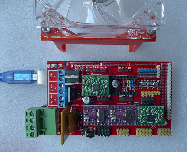
The picture is missing of a Ramps 1.4 board with all of the stepper drivers fitted unless I missed seeing it..?
There are text warnings on the cct diagram about plugging the step-stick/Pololu drivers in the right way round but not one single picture showing "Them plugged in the right way round"
- Here is a picture of a RAMPS 1.4 with a mix of driver boards:
- More info in this page: A4988 vs DRV8825 Chinese Stepper Driver Boards
- --AndrewBCN (talk) 18:37, 19 January 2015 (PST)
The jumper selector section is wrong
The jumper section for drivers is wrong - it can vary for drivers, like DRV8825. Section should mention this.
Small heatsink suggested for Q3 (heatbed MOSFET)
I strongly recommend using a small heatsink for Q3, the MOSFET used for the heatbed. This is because it carries heavy current when On i.e. up to 10A. From the STP55NF06 datasheet, we have the RDS-on (resistance of the junction when the transistor is On) = 0.015 Ohm. This gives us the power dissipation:
PD = I^2 * R or 10 * 10 * 0.015 = 1.5W
and we can calculate the temperature rise of the transistor using the thermal resistance of the TO-220 junction to ambient air again from the datasheet:
Rthj-amb = 62.5°C/W => temperature rise of junction = 1.5 * 62.5 => temperature rise above 90C
This leads us to the conclusion that the Q3 transistor without a heatsink will reach temperatures above 100C while the heatbed is heating up. With even a small heatsink, the transistor's temperature will remain in a safe zone below 65C.
In other words, it's a good idea to add a $0.10 heatsink to Q3 on the RAMPS 1.4 board for your RepRap.
--AndrewBCN (talk) 18:18, 19 January 2015 (PST)
- Or use IRLB8743PBF instead, it's actually cheaper than STP55NF06L.--Manboy (talk) 17:28, 4 March 2017 (PST)
Back EMF, power voltage line
RAMPS design needs Back EMF shield for motor driver, like diodes. And also need seperate 35V input for step diriver.
The current design is faults when step motors has power drain.
Short circuit protection on stepper selection
A defective Pololu driver detonated the 5V regulator on my Arduino. A short between 5V and GND was discovered whenever the defective stepper driver had 5V and GND connected along with RESET, SLEEP, and MS3. Looking at the schematic, SLEEP and RESET are tied together via RAMPS, so my guess is that the MS3 (tied to 5V via step selection jumper) brought 5V into the defective chip, and a path to GND existed within the chip that required SLEEP and RESET to be shorted. Since we are only applying a logic level to the stepper driver, we should put a current limiting resistor in series with the step selection jumpers.
Short circuit protection on endstops
Current limiting resistors should be put between the 5V supply and the 5V pins of the the endstop headers. Many people are accidentally offsetting their connectors by one pin and shorting ground to 5V
24V labeling
The RAMPS 1.4 pinout diagram (https://reprap.org/wiki/File:Arduinomega1-4connectors.png) labels the power inputs and outputs as "12-35 VDC". However, a modification sub-topic indicates a stock RAMPS can only accept 12 V and describes how to convert a RAMPS to 24 V operation. Which is correct? Do recently manufactured RAMPS support 24 V without modification?
