Jy-mcu
This page is a development stub. Please enhance this page by adding information, cad files, nice big images, and well structured data!
Release status: Working
| Description | simplify bt connection to reprap
|
| License | GPL
|
| Author | |
| Contributors | |
| Based-on | |
| Categories | |
| CAD Models | |
| External Link |
Contents
How to print over Bluetooth
One way to cut the cable between your laptop and your RepRap:
Replace
- The USB cable and the FTDI USB-to-TTL-RS232 adapter
with 2 Bluetooth radios:
- Many or most laptops already have a Bluetooth radio built in
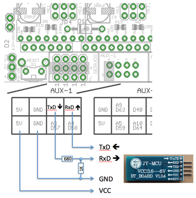
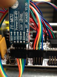
- The TTL-RS232 serial pins of the RepRap controller board can be directly connected to the "jy-mcu" board or similar Bluetooth adapter.
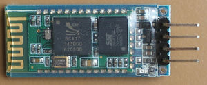
jy-mcu is a board that contains the hardware of the hc-03,hc05,hc06 chipsets. compatibility is the same as they all accept the same at commands, however voltage levels may be different, so use caution if it is not on a board with 4 pin headers.
This is a bt adapter that is used on some reprap with bt connection. Also will provide detailed instructions on how to setup with using android device only.
YOU WILL WANT TO READ COMMENTS IN CODE because there is a line that needs to be changed for it to work and not error out with code stating to read code. this just prevents changing baud rate accidentally when bt device is just plugged in.

Bluetooth is a wireless technology used for short range communications. Bluetooth has protocols that allow it to mimic serial communications and this makes it perfect for use with arduino, and on a ramps board for 3d printing software controls such as pronterface, and repetier host.
Also it allows programing to be done on any device that has arduino ide. this includes PC, Mac, ubuntu, and android.
here is a video of it working on a reprap.
http://www.youtube.com/watch?v=eZO8BniV1xI&lc=ShtOIYGwn4AhHoBuM1LTSm9Suhi8WjYiwIZM74MbKF0
here is a program i made that runs on arduino ide and automatically detects baud rate and sets up device. You will need to manually cut and paste to link to downloads, because of setup change on host web site. http://forums.reprap.org/file.php?156,file=18939,filename=bt_magic_v1.ino,download=1 (bt_magic.ino for arduino)
https://reprap.org/forum/file.php?156,file=111589,filename=bt_magic_uno.ino,download=1 (this version works on uno. was uploaded may31,2019)
runs on version 1 of arduino ide. also serial monitor needs to be at 57600 and set to no line ending. cr and line need to be disabled for serial monitor.
Now there is a version that runs with software serial, so it works on basically anything ported to arduino that can run software serial library. tested on arduino 1.5, but should work as far back as 1.0 i recently updated it so it works on mega,adk,and other arduino devices. still i think that hardware serial version above should be used first. the software serial version as of 1/8/2015 and bt magic still have some issues with communication above 19200 baud. so i would recommend if it detect your bt device, to change baud rate settings last if you use the software serial version. so change device name, password, then change baud rate. I'm looking at my own method to keep communications stable for software serial bt. I'm open to help and suggestions. thank-you!
http://forums.reprap.org/file.php?156,file=46010,filename=bt_magic_update.zip,download=1 (softwareserialbtmagic) recently updated. you will still need to read script before compiling.
here is a video of the program used to setup bluetooth adapter link title
SETUP with android devices requires a ON THE GO CABLE and the following free apps to be installed Arduino Communicator (to setup usb comm), arduino droid, and free usb serial. free usb serial app acts as the terminal because the system monitor does not yet exist in android version of arduino ide.
I will do another video soon (using a better camera), and add multicomm port program ability.
enjoy!. questions or comments or feedback contact me on the forum. thanks!
troubleshooting
if issues with detecting device, first shorten tx/rx lines to be less than 6 inch. If that doesn't work, try changing
if (detect < 2) {x=0; Serial.println("_no");}
to
if (detect < 1) {x=0; Serial.println("_no");}
This allows for detection even when serial receiving timing is off, usually from the dual interrupt. chip should program fine as serial2 data is all sent at once.
On boards version 1.06 and possibly later, the baud rate may not be detected at all. Try adding a pullup resistor to the Bluetooth Module's TX line (the RX line on the Arduino). Even better, you can use the Arduino internal pull-up resistor by adding line pinMode(17, INPUT_PULLUP); to the above Arduino code (see here for more info).
A simple way to change BT module settings - apparently using ftdi chip, but not recommended
(another person recommended this and added changes to this web page. I do not recommend this method below because it could short out pins in the chip, or on the arduino logic board. this being said the boards and the jy-mcu seem to be quite robust.)
Here you take the full advantage of the USB-to-TTL Serial chip of your Arduino board (see Mega or Uno , "Input and Output" section).
You do NOT need a USB-to-TTL Serial converter module (like this one, as described in Melzi), you do NOT need an Arduino program to send commands to the BT module (as described above or in RAMPS).
Procedure:
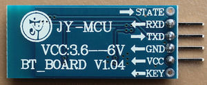
- 1. Connect the BT module to the RAMPS or Arduino board as follows [notes 1, 2]:
BT JY-MCU RAMPS / Arduino VCC 5V GND GND TX TX0 (D1) RX RX0 (D0)
- 2. Arduino must have no programs loaded (e.g. Marlin or other 3D printer firmware) that interfere with Serial0 communication.
- 3. The BT module red light should be blinking (which means no active BT connection to a PC or other device).
- 4. Start a terminal program (e.g. Serial Monitor within Arduino IDE, CuteCom in Linux, TeraTerm in Windows) with the following settings:
- Baudrate 9600 bps (this is usually the default for BT JY-MCU).
- Select 'No line ending' or something similar (AT commands shoud be sent without any other character like CR or LF).
- Baudrate 9600 bps (this is usually the default for BT JY-MCU).
- 5. Make a connection to the BT module and type the following AT commands [notes 3, 4]:
- AT - response should be: OK
- AT+BAUD8 - response should be: OK115200BAUD (set baud rate 115200 bps)
- AT - response should be: OK
- 6. Disconnect, then re-connect with baudrate 115200 bps and check that everything is OK by typing:
- AT - response should be: OK
- AT - response should be: OK
Notes
- 1. Here we make a direct Tx-Tx and Rx-Rx connection (i.e. no crossover); this is OK only for changing BT module settings, while for normal communication between PC and 3D printer you have to make a Tx-Rx connection instead.
- 2. I did not use resistors (a different solution than in RAMPS); some people say this solution is NOT correct/safe???, but it worked well for me with BT modules V1.05 and V1.06 not only for changing BT module settings, but also for normal communication between PC and 3D printer (see also here and here).
- 3. AT commands need to be sent at once (i.e. not single characters at a time). If your terminal program does not allow that, simply copy the command to the clipboard and paste it at once into the terminal.
- 4. Here you find more info about the AT commands.
Tip
I suggest you to use Serial0 (i.e. pins D0 and D1) to connect the BT module to RAMPS / Arduino for normal communication between PC and 3D printer as well, as this will allow you to switch between USB and BT communication without the need to change the serial port number in your firmware (e.g. SERIAL_PORT paramenter in Marlin). However, some versions of the BT module (like V1.05) interfere with the USB communication and you need to disconnect the BT module when you want to communicate via USB (including Arduino firmware upload operation).


