Riki200
Release status: design
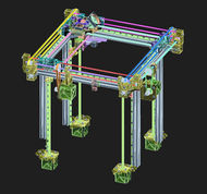
| Description | A fast, accurate aluminum-framed printer with a 200x200x220mm print area using a pulley-enhanced Ultimaker-style Cartesian gantry.
|
| License | |
| Author | |
| Contributors | |
| Based-on | |
| Categories | |
| CAD Models | |
| External Link |
Contents
Introduction
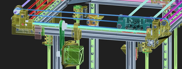
The Riki200 is a high-accuracy high-speed experimental Cartesian 3D printer that uses 2020 aluminum extrusion frame.
Goal
To design a fast, accurate and affordable portable 3D printer using pulley-enhanced Ultimaker-2 kinematics that offers high speed and quality. The printer must be able to be built without specialized tools, and must be completely rigid when assembled.
Features
- Cross-braced Aluminium cube
- Minimal Aluminum structure 20x20mm extrusion for supporting rails
- Triple lead screws and dual rails to provide guaranteed absolute rigidity.
- Ultimaker-2 style pulley-enhanced kinematics for both X and Y, doubling the accuracy and halving belt stretch.
- Swappable X and Y kinematics to use different pulley ratios (2.5:1 or 1:1)
- 200x200x220mm build area with heated bed
- All hardware and electronics (except for filament spool) are integrated within the frame.
- Capable of 0.05mm layer height and 400 mm/s printing
- Emphasis on using 3D-printed parts and being easily hackable/upgradeable
- Flex3Drive to provide *more* than the best of both direct-drive and bowden worlds
- Flex3Drive and an E3Dv6 "volcano" set gives very high flow-rates
- Low moving mass — all motors stationary.
- No specialized tools or equipment necessary for assembly (accessible)
- Linear rails to avoid unnecessary play due to machining tolerances
Hardware Specifications
- 24v low-profile 350W PSU
- 3mm Aluminium MK3 214x214 printbed
- Duet 0.8.5 electronics (high current stepper drivers, up to 30V)
- 84ozin (60Ncm) 200steps/rev 2.5A NEMA17 Stepper Motors (QTY 4)
- E3Dv6 3.0mm Bowden hot-end with "Volcano" upgrade and 0.4mm nozzle (up to 1.2mm available)
- Flex3Drive flexible driveshaft with a 40:1 wormdrive and a MK8 filament drivegear.
Design sketches
Concept 1
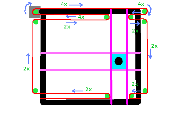
Conclusion: fail. Pulleys separated by 320mm means that there is a 4x force multiplier on one end and a 2x force multiplier on the other. Consequently the force imbalance causes rotation of the assembly as there is nothing impeding rotation.
This is a quick sketch showing the proposed belt layout (duplicated and identical for Y), making this a straight Cartesian design. The notable feature of this concept is the double pulley system and balanced load. The original 1990s Rikidenki scientific plotter design has just one pulley arrangement, with the pulley itself mounted on the carriage, so that the pulley's force acts primarily on the carriage. However if the carriage happens to not be precisely on centre (at left or right extent of travel in the other axis) then the force on that single pulley is not acting on the centre of gravity due to the mass it is acting on also including the rod and idlers.
A double pulley system has two distinct advantages: firstly it quadruples the effective force that can be applied by the stepper motors, but second and perhaps more importantly the force acts equally at the left and right ends of the entire carriage and rod sub-assembly. If the carriage happens to be at the extreme extent on the other axis, resulting in a change in the centre of gravity of the carriage and rod assembly, the forces are not as well-balanced, but with the pulleys acting on the furthest ends this is deemed to be an acceptable design risk.
Prior design concepts had the two pulleys acting on the actual carriage, however it was realised that this required a huge amount of idlers, but also that the force applied by the twin pulleys would be less balanced in an off-centre situation. Placing the idlers on the twin rod holders (mounted on linear rails) would be a simpler and more effective design.
Concept 2
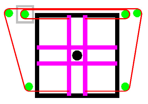
Etch-a-sketch layout. Belts back-to-back on a single GT2-6mm-20t clamped.
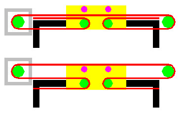
Conclusion: don't put 2 belts back-to-back on the same idler or GT2. Design concept can be fixed as follows:
A full design layout is here:
Concept 3
The concept here is to use twin belts per axis with 340mm 5mm OD rods connecting the two, in a "standard" industrial layout. However a pulley system is to be introduced which will halve the force per belt section as well as double the accuracy. A 40:20 = 2:1 GT2 gear on the 5mm rod will also be deployed along with a closed loop belt, to give extra accuracy.
Analysis
Bill of Materials
The BOM is maintained in the source for the CAD model, and is auto-generated (including an accurate count of nuts and bolts required). A copy is here: http://hands.com/~lkcl/riki200/bom/riki200_model.bom.3.0.pdf
Printed Parts
The STL files are auto-generated from pyopenscad (included in the source). Recent copies may often be obtained here: http://hands.com/~lkcl/riki200/scad/stl/ and http://hands.com/~lkcl/riki200/pulley/ (GT2-6mm-50T.stl). Full source is obtained with
git clone http://hands.com/~lkcl/riki200/.git/
Build requirements: install git, GNU make, python2 and a recent version of openscad. Run "make download" followed by "make".
Tools
Recommended: obtain a small geared power drill or a screwdriver with a standard hexagonal toolbit adapter: there are an enormous number of M3 nuts, bolts and screws to assemble (over 300)
- 1/4in (6.5mm) M3 hex nut/bolt socket: narrow / long type. OD must be no greater than 8mm, extending for at least 10 to 12mm.
- Allen keys: 1.5mm, 2.0mm, 3.0mm, 4.0mm (these are for the MK8 drive gear, GT2 gears, etc. - get 2 of the smaller ones because they tend to wear out)
- Screwdrivers: electrical (for the EC), flat-head and/or pozidrive (for M3 screws)
- M3 spanner(s), adjustable spanner(s), or Pincer-nosed pliers with small eye for nuts (M3) (Qty 2 recommended)
- Another 3D printer capable of 0.20mm layer height (your own or use someone else's)
- Keyfile set (round, square, flat, arc, triangular etc.) and small Craft knife (for trimming 3D parts: keyfiles can also be useful for filing inside extrusion ends, so that M3 hex nuts fit properly)
- Soldering iron, solder, stand and sponge (usual deal for soldering)
Development
Discussion on the reprap forum is here: http://forums.reprap.org/read.php?177,767087
Version 1.0
Initial variant.
TODO investigate
Gallery
A photo gallery is maintained here:
