RepRapPro Tricolour frame assembly
|
English • العربية • български • català • čeština • Deutsch • Ελληνικά • español • فارسی • français • hrvatski • magyar • italiano • română • 日本語 • 한국어 • lietuvių • Nederlands • norsk • polski • português • русский • Türkçe • українська • 中文(中国大陆) • 中文(台灣) • עברית • azərbaycanca • |
Introduction | Frame assembly | Y axis assembly | X axis assembly | Z axis assembly | Heated bed assembly | Extruder drive assembly | Hot end assembly | Wiring | Power supply | Commissioning | Printing | Multi‑colour/multi‑materials | Colour Printing - Slic3r | Colour Printing - RepRapPro Slicer | Maintenance | Troubleshooting | Improvements
| A notice about these instructions! |
|
These instructions are open to editing by everyone and anyone. |
Contents
Goal
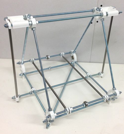
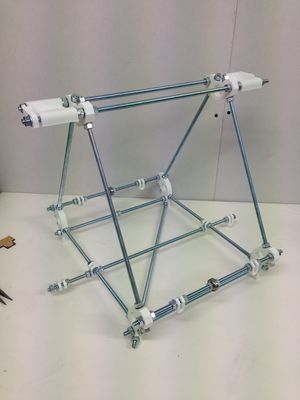
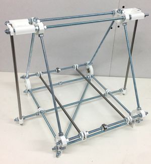
By the end of this stage, your machine should look like this:
Tools
You will need the following tools
- M8 (13mm) spanner
- Adjustable spanner
- 300mm Rule
- Lasercut MDF Measuring template (supplied with kit)
- (optional) Spirit level, cotton and Blu-tack
Step 1: Frame triangles
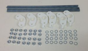
| |
| Item | Quantity |
| 370mm M8 rods | 6 |
| Printed frame vertex with foot | 4 (2 left, 2 right) |
| Printed frame vertex | 2 |
| Printed Bar Clamps | 2 of 8 |
| M8 nuts | 28 |
| M8 lock washers | 28 |
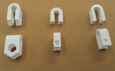
Note that there are three types of printed U clips in your kit:
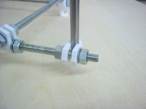
The ones on the left are the Bar-Clamps (8Off), the ones in the middle are the PCB clips (3Off), and the ones on the right are the Frame clips (2Off). For this step you want the ones on the left.
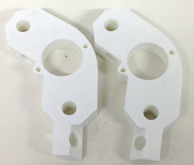
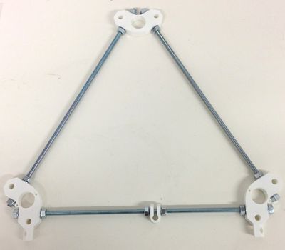
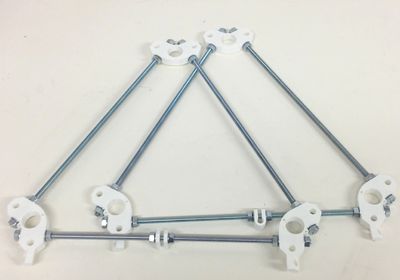
Split the components into two equal sets. The footed frame vertices are not all the same; there are two pairs. For each frame triangle, use a pair of vertices with feet that point in different directions as shown below.
Also, make sure you slide a Bar clamp along the bottom M8 threaded bars between the frame vertices with feet, with a lock washer and nut either side. The other nuts should also all have lock washers under them. Loosely screw together each frame triangle.
Make the gap between the frame vertices measured face to face next to where the nuts and washers tighten about 290 mm.
Your kit has a template to make it easy to get these measurements right.
Don't tighten anything at this stage.
Step 2: Cross bars
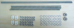
| |
| Item | Quantity |
| 330mm M8 rods | 4 |
| 470mm M8 rods | 2 |
| Printed Bar Clamp | 4 or 8 |
| 8mm bearings | 2 |
| M8 lock washers | 24 |
| M8 nuts | 26 |
The figures in brackets are the numbers if you want to add clamp nuts across the top bars (see below).
Assemble the bars as shown in this picture:
From top to bottom and left to right the sequences are:
- Lock washer, nut, nut, lock washer
- Lock washer, nut, nut, lock washer
- Lock washer, nut, nut, lock washer, Bar Clamp, lock washer, nut, nut, lock washer, bearing, lock washer, nut, nut lock washer, Bar Clamp, lock washer, nut, nut, lock washer
- Lock washer, nut, nut, lock washer, lock washer,nut, nut, lock washer
- Lock washer, nut, nut, lock washer, Bar Clamp, lock washer, nut, nut, bearing, nut, nut, lock washer, Bar Clamp, lock washer, nut, nut, lock washer
- Lock washer, nut, nut, lock washer.
Step 3: Put them all together
| Item | Quantity |
| M8 nuts | 12 |
| M8 lock washers | 12 |
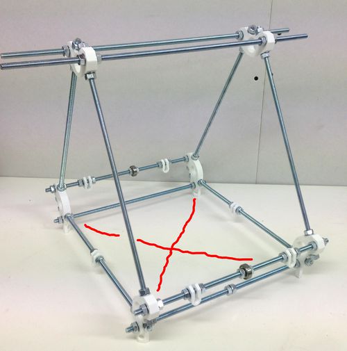
Slide all the cross bars into one of the triangles as shown below, and secure lightly with a locking washer and nut on each rod end. Next slide the second triangle onto the other end of the cross bars; use a locking washer and a nut on each rod end. The holes in the feet should line up to form an X as shown in red below.
Using the numbers of the rods from Step 2:
At the top attach the two long Rods: 1 and 2.
Back top: Rod 3
Back bottom: Rod 4
Front top: Rod 5
Front bottom: Rod 6
Now go round the frame tightening everything up using two spanners. Tighten the triangles first, then the six bars connecting the 2 triangles in the x direction.
Use the template to get the measurements right.
Make the gap between the faces of the vertices on the triangles 290mm, as mentioned above. Make the gap in the x direction between the faces of the vertices 273mm.
Get the two top rods even, with an equal amount projecting each side, then move the back one 5mm to the right and the front one 5mm to the left.
Try to get the measurements accurate. But it is more important to get the lengths equal than to get them precise.
Step 4: Z-motor mounts, diagonal, and power connector
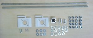
| |
| Item | Quantity |
| 470mm M8 rods | 2 |
| Printed Z motor Mount | 2 |
| Printed Bar Clamp | 2 of 8 |
| M8 nuts | 16 |
| M8 lock washers | 14 |
| M8 washers | 10 |
| XLR panel plug | 1 |
| 20mm M3 caps | 2 |
| M3 washers | 2 |
| M3 nuts | 2 |
Put the two Bar Clamps on the bottom rods of the frame triangles roughly in the middle of their bars. Using a 470mm rod, thread it through the two Bar Clamps, with a nut and lock washer each side. You may have to twist the rod to get it through the Bar Clamps, using its thread to move it - it can be quite a snug fit. Secure the rod to the frame with another lock washer and nut on the outside of each Bar Clamp.
Use nuts and lock washers to put two more Bar Clamps on its ends for the Z smooth rods, as shown below. Leave all these lose.
The order of parts on the lower rod should be:
nut, lock washer, Bar Clamp (for z smooth rod), lock washer, nut, nut, lock washer, Bar Clamp (frame), lock washer, nut - (gap between frame triangles) - nut, lock washer, Bar Clamp (frame), lock washer, nut, nut, lock washer, Bar Clamp (for z smooth rod), lock washer, nut
Next thread the base diagonal rod through two of the four feet. Put nuts and lock washers on it both inside and outside each foot, but leave them lose.
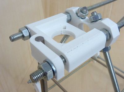
Put eight smooth washers on the top bars, with two on either side of each rod then put the Z motor mounts on.
Secure them with two nuts each, with one smooth washer and one lock washer. The smooth washer goes on the clamp that will hold the Z rods. Tighten the other nuts against their lock washers, but leave the Z-rod-clamp nuts lose.
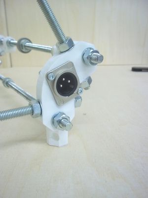
Fit the XLR plug to the frame vertex at the rear right of the machine with the socked facing outwards, i.e. this is the side with the nuts on the bottom bar and on the foot with the diagonal cross brace, using the M3 screws, nuts and washers. The washers go under the nuts. Fit the plug so that the triangle formed by its three pins points upwards.
Step 5: Smooth rods

| |
| Item | Quantity |
| 400mm smooth rods (Y) | 2 |
| 350mm smooth rods (Z) | 2 |
If the ends of the rods are sharp from cutting, use a file to smooth off the ends to give a small conical chamfer (0.5 .. 1 mm). Without it, there is a risk of unseating the balls inside linear bearings while inserting the rods.
Adjust the U clips for the Y rods at the front and back of the frame so that the gaps between their outer nuts and the nuts on the frame vertices are about 20mm. Slide the Y rods through. Don't tighten them.
Next place the frame on a flat surface. Wooden furniture, by and large, is not flat. But thick kitchen worktops are very flat.
Chances are that the frame will rock slightly about one or the other diagonal.
Tighten the diagonal bar in such a way as to stop the rock. If the frame rocks about the bar's diagonal, the gap between its nuts needs to be bigger. If the frame rocks about the opposite diagonal, the gap between the diagonal nuts needs to be smaller.
Adjust the U clamps on the left-hand Y rod so that their nuts are 22mm from the nuts on the left frame triangle, and then adjust the right-hand Y rod U clamps so there is 175mm between the rods. Leave the clamps lose.
Aligning the Z Rods
You can now slide the two Z smooth rods into place. Do not over-tighten the clamping nuts on the Z motor mounts. The rods need to be held firm, that is all.
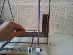
Use a set-square to get the angle of the Z smooth rods correct.
You can now tighten the M8 nuts along the bottom cross bar.
Frame finished
You will now have an assembled RepRapPro Mendel frame (though the smooth Y rods and the bearings will still be lose):
