RepRapPro Mendel Mini Extruder
Introduction | Frame assembly | Y axis assembly | X axis assembly | Z axis assembly | Heated bed assembly | Extruder drive assembly | Hot end assembly | Power supply | Wiring | Commissioning | Printing | Multi‑colour/multi‑materials | Colour Printing - Slic3r | Colour Printing - RepRapPro Slicer | Maintenance | Troubleshooting | Improvements
| A notice about these instructions! |
|
Since 1st April 2013, the RepRapPro Mendel has been superseded by the RepRapPro Tricolour and Mono Mendel. |
Contents
Alternatives
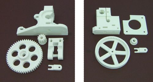
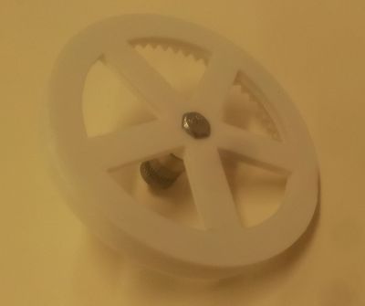
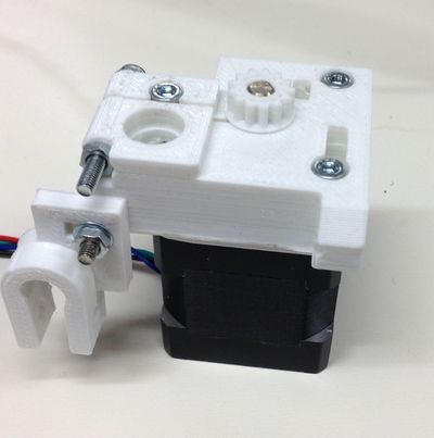
There are two types of extruder drive available for RepRapPro Mendel, the printed parts for which are shown left and right above.
If you have the printed parts shown on the right, your instructions are on this page.
If you have the printed parts shown on the left, then go here.
Goal
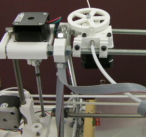
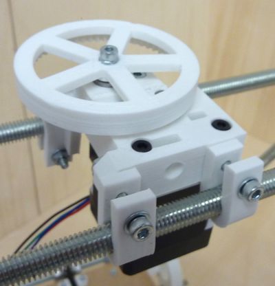
By the end of this stage your extruder drive will be mounted on the top of your Mendel like this:
But without all of the wires.
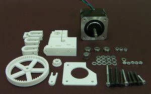
Step 1: Components
Step 2: Assembly
Start by assembling the geared filament drive.
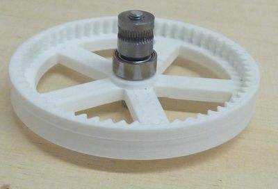
Take the 20mm M3 hex screw and insert it into the large drive gear. Make sure the flats of the hex head are aligned with the hexagon of the recess. Put the 20mm M3 hex screw with the thread running all the way to the top through the nut then screw on the other parts. The order goes:
- Hex head
- Gear
- 623 bearing
- Hobbed insert
You will notice that the hobbing on the insert is not in its centre. Put the insert on so that the hobbing is away from the gear end and the conical chamfer is against the bearing. After putting the bearing on, but before the hobbed insert, place a small blob of superglue or threadlock on the screw threads, about 5mm from the bearing. Then screw on the hobbed insert.
Do the hobbed insert up tight with your fingers.
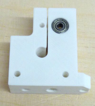
Next put a 623 bearing in the back of the drive block as shown. You may need to clean the hole a little. Use a 10mm drill bit twisted carefully in the hole by hand. While you are at it, clean the hole at the other side too.
Push the gear and hobbed insert assembly that you just made into the opposite side of the block to the one that you just put the bearing into. Check that the hobbing is centred where the filament will run by looking in the unoccupied idler bearing hole in the side of the drive block (poke a length of filament down the 2mm hole in the top of the block if you can't tell where this is).
Take the gear and hobbed insert assembly out of the block for the moment.
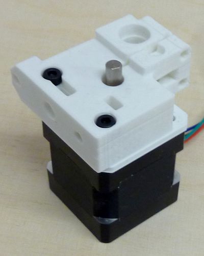
Mount the block on the motor as shown above using two 16mm M3 cap screws. Put the spacer between the block and the motor. The motor wires are at the back right in this picture.
Fit the idler bearing using the 12mm M3 cap screw as shown (the screw needs no nut to retain it).
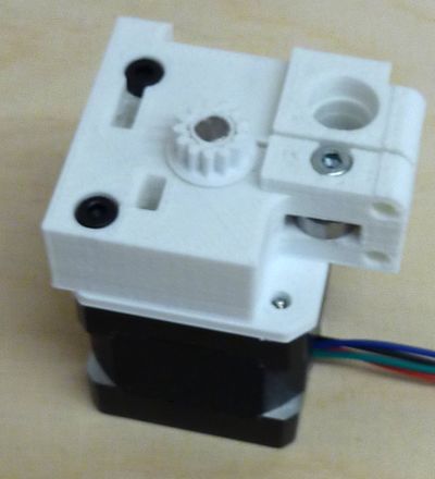
Fit the small gear. You may find this easier if you use a sharp blade to put a slight chamfer on the underside of the gear where it meets the motor shaft.
Push the small gear onto the shaft such that its top is flush with the end of the shaft. You may need to tap it with a soft hammer or block of wood - take care, and support the back of the motor shaft as you do this, rather than the motor's body.
Push the gear and hobbed insert assembly into its hole in the block. Rotate the gear as you do this so that it meshes with the small gear on the motor.
Note that the gear and hobbed insert assembly is designed so that the action of driving the filament tends to tighten the hobbed insert on the M3 thread. It can also be easily removed for cleaning when there is no filament in the drive. But when it is operating the filament that it is driving retains it in place by lying in the slight dent formed by the hobbing.
Step 3: The Bowden tube
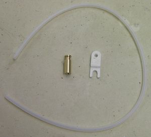 Don't confuse the PTFE tube (shown) with the shorter translucent heatshrink also supplied with the kit. | |
| Item | Quantity |
| Tongue (printed) | 1 |
| slotted brass retainer | 1 |
| PTFE tube | 1 |
Use a sharp blade to trim a few millimetres off the end of the tube at right angles to get a clean square end.
Screw the tube into the brass retainer. Look in the other end (a magnifying glass is useful) to see when it gets to the end of the internal thread, then stop. If you have trouble starting the threading, make a small cone on the end with a pencil sharpener. Don't cut too far - PTFE is very soft. The cone makes it easier to start the thread.
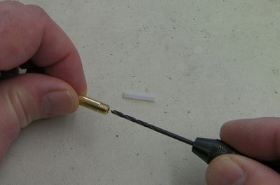
Screwing the tube in will have reduced its internal diameter slightly. Gently twist a 2mm drill by hand in the end of the brass to thin the tube where it is inside the screw thread. If you have a small hand-chuck this is made easier. The picture shows this being done for the other brass connector that you will install on the next page. The method is the same:
Push a short length of 1.75mm build filament down the tube from its free end to clear out any PTFE swarf, and to check the filament moves smoothly.
Push the brass retainer into the drive, and secure it with the printed tongue in the hole above. The thin end of the tongue goes towards the front in the picture at the top of this page, locking the brass retainer in place:
Idler Tensioning
In order to tension the idler mechanism, tighten the two M3 cap screws and nuts mentioned earlier until the point that the drive block has sufficiently flexed that no gap is visible.
Feed a length of filament through the drive by turning the big gear by hand. When you hold the gear still, it should not be possible to pull the filament back out of the drive by hand. If it slips, tighten the two nuts slightly.
Fitting the drive
Use the three U clips together with cap screws nuts and washers to mount the drive on the top two frame bars of your Mendel as shown. You can do this with the large gear removed, to make it easier.
The two holes above the large gear hole act as the idler tensioners. One of the also secures the extruder to the frame. Put a 30mm M3 cap screw and washer into the hole nearest the gears, with a nut (no washer) in the groove on the other side. Leave this loose for the moment.
In the hole closest to the motor, use a 35mm M3 cap screw and washer, put the tabbed frame clip on the opposite side with the screw going through the tabbed part, secured with a nut and washer.
Tighten the nuts on both of these screws until they just touch the surface against which they bear, but no tighter. Later you can adjust these for idler tension on the filament.
Clip the tabbed frame clip over the frame, and secure the clip with a 20mm M3 cap screw and washer, and a nut and washer
Clip the other two frame clips onto the front piece of studding at the top of the machine. The block is secured to one clip by dropping an M3 nut into the upper slot shown on the picture above and using a 35mm M3 cap screw. The other is secured by a 30mm M3 cap screw with a washer, and a M3 nut and washer on the other side as shown above.
Multi-colour/Multi-material Mendel
If you are building the multi-colour/multi-material version of RepRapPro Mendel then you will need three drives in total. Build two more as described above and fit them evenly spaced along the top bars of the machine: left, middle and right.
