RepRapPro Huxley frame assembly/fr
Introduction | Assemblage châssis | Assemblage axe Y | Assemblage axe X | Assemblage axe Z | Assemblage du plateau chauffant | Assemblage de l'extrudeuse | Assemblage des pièces chaudes | Câblage | Mise en service | Impression | Maintenance | Résolution des problèmes | Améliorations
| A propos de ces instructions! |
|
Ces instructions peuvent être modifiées par tout un chacun. |
Contents
Objectif
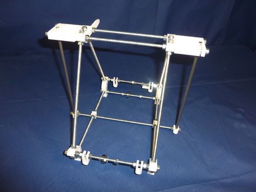
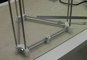
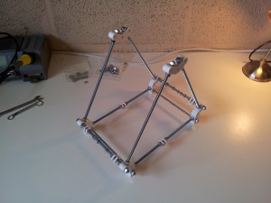
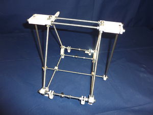
A la fin de cette étape, votre machine devrait ressembler à celà:
Outils
Vous allez avoir besoin des outils suivants
- Gabarit de mesure découpé au laser (fourni avec votre kit)
- Clé plate de 10mm (M6)
- Clé à mollette
- Equerre
- Règle de 300mm
Etape 1: Triangles chassis
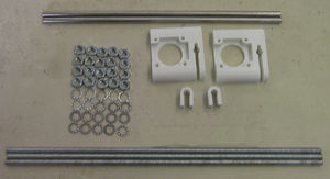
| Pièces RP | Quantité | 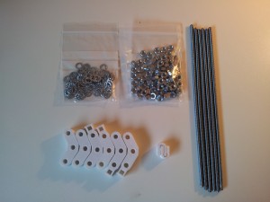
|
|
2 | |
|
4 | |
|
2 | |
| Matériel | Quantité | |
| Tiges filletées M6 x 250mm | 6 | |
| Ecrous M6 | 28 | |
| Rondelles frein M6 | 28 |
Construction de 2 jeux de triangles (5 min chacun)
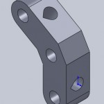
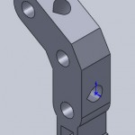
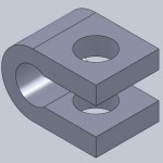
Séparez les 6x composants plastiques RP en forme de V en deux groupes égaux de 3x (1x la partie gauche avec pied, 1x la partie droite avec pied et 1x la partie supérieure), commencez avec les 2 pieds, assurez-vous de glisser un dispositive de serrage (pièce plastique en forme de U) le long du bas de la tige filletée M6 de 250mm, avec une rondelle frein et un écrou de l'autre côté, puis vissez sans serrer avec vos doigts le reste de la tige de 250mm dans chacun des 3x composants plastiques RP en forme de V pour finalement former un triangle.
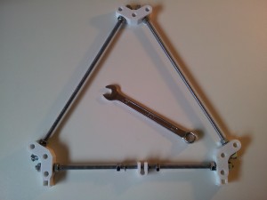
Quand vous aurez placé une rondelle frein entre la pièce RP en forme de U et chaque écrou M6 vous devrez obtenir ceci:
Répétez maintenant l'opération pour le second triangle, vos triangles de chassis devrait ressembler à ceci:
Ajustement fin des 2 tailles de triangle (20 -30 min)
Avant de passer à l'étape suivante, nous devons resserrer les boulons à la bonne distance sur les deux triangles du chassis pour les rendre rigides.
Votre kit contient un gabarit de mesure découpé au laser. Vous pouvez l'utiliser pour vous faciliter la vérification de l'espacement. Si vous faites un assemblage personnalisé, la meilleur alternative est de découper un dispositif de mesure de 207mm de long dans une tige de bois de 1m de long et 8mm d'épaisseur.
Soyez patient, prenez votre temps, cette étape est très importante.
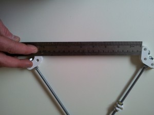
Pour chaque cadre, mesurez la distance entre les sommets des trois côtés. La distance que vous devez obtenir est de 207mm. Mais le plus important est que tous les six soient exactement les mêmes. Mieux votre cadre sera aligné, meilleures seront vos impressions quand vous imprimerez des objets grands et/ou petits.
Serrez doucement tous les écrous M6 en vous Assurant que la distance de 207mm entre les sommets est respectée.
Un truc assez pratique une fois que vous avez serré précisément un triangle est d'utiliser les autres tiges de 6mm du kit pour aligner le deuxième:
Utilisez les 6 tiges lisses plutôt que celles qui sont filletées pour plus de précision, mais assurez-vous que les tiges lisses peuvent être insérées sans aucune pression dans les trous. Dans le cas où vous n'avez pas suffisament bien preparé les trous et que vous persistez à pousser les tiges lisses à l'intérieur n'utilisez aucun outil sur elles directement pour les ressortir - prenez un tissus, entourrez les et ressortez les délicatement en effectuant un mouvement de rotation.
Pour les assemblages personnalisés si vous avez des vis à tête hexagonale M6, vous pouvez les utiliser au lieu de vos précieuses tiges lisses.
Etape 2: Barres de traverse
| Pièces RP | Quantité | 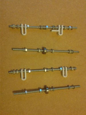 |
|
3 | |
|
1 | |
| Matériel | Quantité | |
| Tige filletée M6 x 185mm | 4 | |
| Ecrous M6 | 24 | |
| Rondelles freins M6 | 24 | |
| Roulements 626 | 2 |
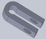
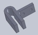
A nouveau séparez les composants ci-dessus en deux jeux égaux, mais avec les deux serres-barres RP en formes de U dans un seul jeu, et une serre-barre RP en forme de U plus une avec une languette dans l'autre. (La languette est pour le contact de fin de course de l'axe Y.) Vous allez assembler les deux barres supérieures (identiques sauf pour le U/U+languette), et les deux barres inférieures (identiques).
NOTE : La languette sur un serre barre en forme de U est utilisée pour maintenir le contact de fin de course de l'axe Y. Installez le maintenant (voir Câblage - étape 5 [1])
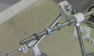
Donc pour une barre supérieur, vous allez avoir besoin (en commençant par le milieu de la tiche filletée M6): rondelle frein, deux écrous M6, rondelle frein, serre-barre, rondelle frein, deux boulons M6, rondelle frein. Puis, dans l'autre direction: rondelle frein, deux écrous M6, rondelle frein, serre-barre+languette (avec la languette en face du centre de la barre), rondelle frein, deux écrous M6, rondelle frein.
Pour la deuxième barre supérieure, vous allez avoir besoin (en commençant par le milieu de la tiche filletée M6): rondelle frein, deux écrous M6, rondelle frein, serre-barre, rondelle frein, deux boulons M6, rondelle frein. Puis faites exactement la même chose dans l'autre direction.
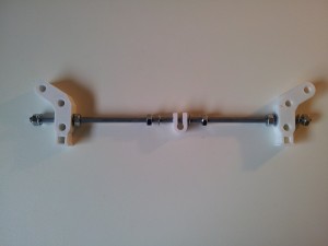
Et pour les barres inférieures: 1 x roulement 626, rondelle frein, 2 x écrous M6, rondelle frein, (puis répétez dans l'autre direction, sauf pour le roulement).
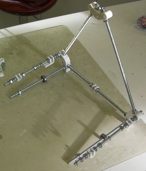
Vos barres de traverse doivent ressembler à ceci:
Etape 3: Mettre tout ensemble
Tout d'abord vissez les barres de traverse dans un des trianqles. La barre de traverse avec le serre-barre doit aller à l'arrière, avec le serre-barre avec la languette sur la droite.
Puis vissez le second triangle à l'autre extrémité des barres de traverse:
Now we need to slide the two top bars through the top frame vertices. Slide each bar through one vertex, then fit one serrated washer, two M6 nuts and another serrated washer before sliding the bar through the opposite vertex.
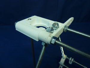
Next, slide a Z motor mount onto each ends of the top bars. This may need a little force as the holes through the z motor mounts tend to be quite a tight fit on the M6 threaded bars (it's usually a good idea to make sure you can push a spare length of M6 threaded bar into each of the z motor mount holes before trying to fit them to your frame).
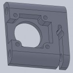
Add the filament drive bracket so it is inside the left Z motor mount and frame-vertex, and is held against it by the inner nuts and washers. The front slot next to the rounded end goes upwards, the middle slot goes at the back and downwards. Imagine hanging a weight on the projecting end - the slots need to go in the way that makes the weight tend to pull things into place, not to release them.
Before tightening the M6 nuts on the top bars, slide the bottom cross bar through the two bottom bar clamps. You do not need M6 nuts or washers either side of these bar clamps. At each end of this bottom cross bar, fit an M6 nut, a serrated washer, a bar clamp, a serrated washer, and another M6 nut.
At this stage, the frame should be quite loose, so just jiggle everything around until it all the angles look about right. Once you are happy with this step, you can tighten the nuts on the cross bars. The distance between the frame vertices along the cross bars should be 146mm. When tightening the M6 nuts on the top cross bars, please note that you do not need to tighten the nuts which clamp against the Z smooth rods too much, only enough to stop the smooth rod from sliding down. If you slip two washers into the groove on the Z-motor mount (with the threaded rod run through their holes) you will be able to clamp your frame solidly and grip the Z-rods without over-stressing the plastic. Your kit doesn't come with these washers. 1/4" washers work well for this.
Before tightening the bar clamps on the bottom cross bar, slide the Y axis smooth rods (270mm) into place. (These are easily confused with the X axis rods, which are 265mm - get the right ones.)
Aligning the Z Rods
Check all of the smooth rods. If the ends of the rods are sharp or burred from cutting, use a file to smooth off the ends to give a small taper/bevel/chamfer; 1mm is fine. Without it, there is a risk of unseating the balls inside linear bearings while inserting the rods.
Check that the linear bearings slide smoothly on each of the smooth rods. The linear bearings may need a little extra oil, and the smooth rod may need cleaning, for smooth running. The quick way to clean the smooth rod is to put it in an electric drill, then use wire wool or a kitchen scourer on it while the drill turns the rod. Be careful though!
You can now slide the two Z smooth rods (length 235mm) into place.
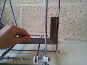
Use a set-square to get the angle of the Z smooth rods correct. Make sure you get the right smooth rod for the Y-axis; if you swap them you will have to go back and take things apart again.
You can now tighten the M6 nuts along the bottom cross bar.
Alternative alignment method
Some people swear by this method, others hate it...
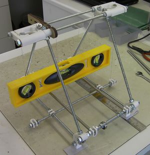
For this you will need the spirit level, two pieces of cotton, and a small blob of Blu-tack.
Build the frame as above, as far as "Aligning the Z Rods".
Place the frame on a flat surface (40mm-thick Formica-covered kitchen worktops are remarkably flat). You will almost certainly find that the feet aren't quite level and that the frame rocks a little about a diagonal. Tightening the frame has distorted it slightly.
Put an object about 10mm high under a foot on that diagonal, and very gently push the other two diagonal corners down. Try the feet on the flat surface again. Repeat this until the frame does not rock, but instead sits four-square on the surface. You can carry out this process at any future stage in the build to re-square the frame.
Put the spirit level across the Y smooth bars, and place folded paper shims under the left or right feet until the frame is level left-right. You will discover that a spirit level is an exquisitely sensitive instrument, and that it can easily detect a couple thicknesses of paper.
Rotate the spirit level through a right angle so it rests between the front and back cross bars, and get the frame level front-back too.
Check the frame is level in both directions.
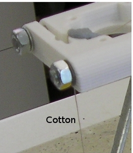
Now thread two lengths of cotton down through the top bracket and the U clamp on the bottom where the Z axis smooth rods will be. Attach it to the Z-axis-smooth-rod holes at the top with Blu-tack such that it is half-way round the inside of the clamp arc.
Put a small blob of Blu-tack on the bottom of each piece of cotton to act as a plumb weight.
Now adjust the positions of the threaded rod at the bottom and the Z-axis-smooth-rod U clamps so that the cotton falls freely in the middle of the U-clamp holes.
Tighten the nuts on the main frame holding the threaded rod, making sure that the cotton stays in the middle of the holes where it was.
Now tighten the inner nuts to move the U clamps outwards so that the cotton just kisses the edge of the U holes in exactly the same relative position as it is falling through the clamps at the top of the frame.
Slide the Z-axis rods in, tighten the clamps from the outside, and check with a square as in the section above. If you've done everything carefully there should be little or no discrepancy, but it is more important to have a right angle than to have the Z-rods plumb.
Frame finished
You will now have an assembled RepRapPro Huxley frame:
