Gen7 Board-AVR 1.5
|
English • العربية • български • català • čeština • Deutsch • Ελληνικά • español • فارسی • français • hrvatski • magyar • italiano • română • 日本語 • 한국어 • lietuvių • Nederlands • norsk • polski • português • русский • Türkçe • українська • 中文(中国大陆) • 中文(台灣) • עברית • azərbaycanca • |
Gen7 Board 1.2 | Gen7 Board 1.1 | Gen7 Board 1.0
Release status: working
| Description | Generation 7 Electronics
|
| License | |
| Author | |
| Contributors | |
| Based-on | [[]]
|
| Categories | |
| CAD Models | |
| External Link | (none)
|
This is the central part of Generation 7 Electronics. A single board with all the features required to run a printer and also including a header to plug in extension boards for future expansion.
How to get it


All these shops support Gen7 development:
- RepRap DIY ( Traumflug's outlet )
- Paoparts
- eMotion Tech
They have PCBs, components and connector kits available. And thank you to these for supporting Generation 7 Electronics development.
PCBs
As Gen7 is designed to be manufactured on a RepRap, you can make PCBs yourself, of course. How to do this on a RepRap or a general milling machine is described on the Gen7 main page. Gerbers, PDFs and such are in Gen7's Github repository.
Yet another way is to purchase from one of the many houses specialized in manufacturing prototype PCBs. Gen7 is single sided, so this won't cost a fortune. If you want to sell excess copies, ask Traumflug for a commercial license.
Components
If you want to assemble the collection yourself, see the Parts Lists section.
Parts Lists
To assemble or verify these lists, open the layout with gEDA/PCB and export a "BOM". This will give you a list of all required components.
Special considerations:
- The Pololu Stepper Drivers come with their male headers, so there's no need to purchase them separately.
- Resistors with 0.25 W are on the safe side, even if the footprint name reads "0.125".
- The Pololus can be operated with up to 35 V, so you may want like-rated electrolytic capacitors.
- Pololus require heatsinks, so make sure you get them with the Pololus or get separate ones.
Electronic Components
This list is ordered to match the order of assembly.
| Name | Count | Designations | Vendors | Remarks | |||||
|---|---|---|---|---|---|---|---|---|---|
| MCP2200 I/SO | 1 | U2 | Reichelt | Farnell | RS | Digi-Key | Mouser | This is the USB-TTL adapter | |
| 0.6 mm Wire | 50 cm | Völkner | Digi-Key | Mouser | for the wire bridges on single sided PCBs | ||||
| Resistor 10 Ohms | 2 | R11, R12 | Reichelt | RS | |||||
| Resistor 560 Ohms | 2 | R14, R22 | Reichelt | Völkner | Farnell | RS | Digi-Key | Mouser | |
| Resistor 1 kOhms | 8 | R1, R2, R4, R6, R8, R10, R16, R18 | Reichelt | Völkner | Farnell | RS | Digi-Key | Mouser | |
| Resistor 4.7 kOhms | 2 | RT1, RT2 | Reichelt | Völkner | Farnell | RS | Digi-Key | Mouser | |
| Resistor 10 kOhms | 2 | R3, R30 | Reichelt | Völkner | Farnell | RS | Digi-Key | Mouser | |
| Diode 1N4004 | 2 | D1, D2 | Reichelt | Völkner | Farnell | Digi-Key | Mouser | ||
| Coil 10 uH | 1 | L1 | Reichelt | Farnell | Digi-Key | Mouser | |||
| Crystal 12 MHz | 1 | U7 | Same housing as the one below, the number on the part reads the frequency. | ||||||
| Crystal 16 MHz or 20 MHz | 1 | U6 | Reichelt | Völkner | Farnell | Digi-Key | Mouser | ||
| Reset Switch | 1 | RESET | Reichelt | Völkner | Farnell | RS | Digi-Key | Mouser | |
| Ceramic Capacitor 0.1 uF | 13 | C8, C9, C10, C11, C12, C13, C14, C16, C17, C18, C19, C20, C21 | Reichelt | Völkner | Farnell | RS | Digi-Key | Mouser | |
| LED 3 mm Green | 5 | RxLED, TxLED, LED2, LED5, +5V | Reichelt | Völkner | Farnell | Digi-Key | Mouser | ||
| LED 3 mm Yellow | 1 | Standby | Reichelt | Völkner | Farnell | Digi-key | Mouser | ||
| Ceramic Capacitor 22 pF | 4 | C3, C4, C5, C15 | Reichelt | Völkner | Farnell | RS | Digi-Key | Mouser | |
| Electrolytic Capacitor 10 uF | 2 | CT1, CT2 | Reichelt | Völkner | Farnell | Digi-key | Mouser | ||
| Electrolytic Capacitor 100 uF | 4 | C1, C2, C6, C7 | Reichelt | Völkner | Farnell | Digi-Key | Mouser | ||
| Jumper Header 2 Pin Pairs | 4 pair | J2/J3, J5/J6, J8/J9, J11/J12 | Reichelt | RS | Digi-Key | Mouser | cut them into appropriate pieces | ||
| Jumper Header 2 Pin | 2 | J13, J14 | Reichelt | Völkner | RS | Digi-Key | Mouser | cut them into appropriate pieces | |
| Jumper for the two above | 9 | Reichelt | RS | Digi-Key | Mouser | ||||
| ICSP Header | 1 | CONN6 | Reichelt | RS | Digi-Key | Mouser | alternatively, assemble this out of the remainings of the Jumper 2 Pin Headers | ||
| Pololu Header | 8 or 4 | U2, U3, U4, U5 | Reichelt | Völkner | Digi-Key | Mouser | cut them to appropriate length if needed, you want 8x 8 pins | ||
| Socket for the ATmega | 1 | U1 | Reichelt | Völkner | Farnell | Digi-Key | Mouser | ||
| ATmega 1284P-PU | 1 | Reichelt | RS | Mouser | |||||
| Alternative: ATmega 644-20PU (or 644P-20PU) | 1 | Reichelt | Farnell | Digi-Key | Mouser | ||||
| MOSFET IRLB 8743 | 2 | Q1, Q2 | RS | Mouser | |||||
Connectors
| Name | Count | Designations | Vendors | Remarks | |||||
|---|---|---|---|---|---|---|---|---|---|
| Molex KK100 2 Pin Header | 2 | TEMP_EXT, TEMP_BED | Reichelt | RS | DigiKey | Mouser | |||
| Cable Connector for the above | 2 | Reichelt | RS | DigiKey | Mouser | ||||
| Crimp Contact for the above | 4 | Reichelt | RS | DigiKey | Mouser | ||||
| Molex KK100 3 Pin Header | 3 | X_MIN, Y_MIN, Z_MIN | Reichelt | RS | DigiKey | Mouser | Reichelt are tested to be fully compatible with Molex | ||
| Cable Connector for the above | 3 | Reichelt | RS | DigiKey | Mouser | ||||
| Crimp Contact for the above | 9 | Reichelt | RS | DigiKey | Mouser | same as for TEMP_EXT, TEMP_BED above | |||
| Molex KK100 4 Pin Header | 4 | X_MOT, Y_MOT, Z_MOT, E_MOT | Reichelt | RS | DigiKey | Mouser | |||
| Cable Connector for the above | 4 | Reichelt | RS | Mouser | |||||
| Crimp Contact for the above | 16 | Reichelt | RS | DigiKey | Mouser | ||||
| USB-B Connector | 1 | CONN1 | Reichelt | ||||||
| Heater Header Molex 26-48-1045 (2 Pin) | 2 | HEATER_EXT, HEATER_BED | RS | DigiKey | Mouser | ||||
| Cable Connector for the above | 2 | RS | DigiKey | Mouser | |||||
| Crimp Contact for the above | 4 | RS | DigiKey | Mouser | |||||
| Alternative to Heater Header: 2 Pin Screw Terminal | 2 | HEATER_EXT, HEATER_BED | Reichelt | DigiKey | Mouser | ||||
| Disk Power Header | 2 | CONN2, CONN3 | Reichelt | RS | DigiKey | Mouser | also see DIY 4 pin molex connector | ||
| ATX24 Power Connector | 1 | CONN1 | RS | DigiKey | Mouser | Molex Mini-Fit 44206-0007. Also known as VAL-U-LOK (20 or 24 Pins). | |||
Miscellaneous
As of v1.5, Generation 7 Electronics has an USB-TTL adapter on board. To connect your Gen7 with a PC, you need just a generic USB device cable.
Last not least, you need four stepper drivers, of course:
| Famous "Pololus" | Pololu stepper driver boards |
|---|---|
| Open Source Alternative | StepStick |
Assembly Instructions
Everything lying around, in bags or single parts? Fine. Let's heat up the soldering iron.
General Notes on Assembly
- To find out which components to put where, have the layout on your PC screen available.
- PCBs fabricated with Voronoi paths need more heat, so raise your soldering iron's temperature by about 20 deg Celsius.
- To ease soldering jumper headers and similar components, put a small drop of cyanacrylate glue onto the component side before inserting them. As the PCB is single-sided, this won't hurt the solder point.
- When soldering parts with many pins, like the ATmega socket, it's good practice to start with the four corner pins, recheck the fit, then soldering every other pin first, before completing the remaining ones. This keeps heat and strain to a minimum.
- Start with the flattest parts, usually wire bridges or resistors. This way, components won't fall out when you lay the PCB on it's front for soldering. Then continue with parts of raising height, connectors are usually among the last ones.
- The parts lists are sorted with that in mind, simply start at the top and assemble towards the bottom.
Assembly in Detail
Caution: Don't solder MOSFETs or insert the ATmega until after the Power Supply Checks.
Click on the pictures to view them larger.
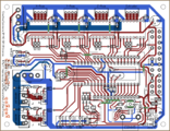
This is the layout, seen from top. If you're unsure, always refer to this picture of the layout. The designators match those in the parts list.
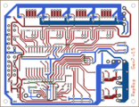
This is the layout, seen from the bottom. Note the MCP2200 on this side.
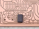
This picture shows how to place the MCP2200. The dot indicating pin 1 is in the lower right corner. For soldering tips, see instructions for the EB-USB-B.
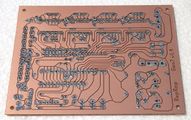
For best solder quality, tin all remaining solder points before inserting components. The picture shows the Gen7 v1.4 board.


- Start with the 9 wire bridges. The layout shows them as matte green tracks. The tracks inside the reset switch are not wire bridges, this connection is established by the switch its self.
| 10 Ω | 560 Ω | 1 kΩ | 4.7 kΩ | 10 kΩ |
| brown-black-black | green-blue-brown | brown-black-red | yellow-violet-red | brown-black-orange |
- D1 and D2 are diodes, so you have to take care of polarity. Diodes have a white ring on the housing, which must end up closer to the boards boundary.
- L1 looks like a thick resistor, but is actually a coil.
- As LEDs are diodes, too, direction matters. The longer of their legs is plus (+), which should go into the hole marked + in the layout.
- Electrolytic capacitors have a polarity as well. The white stripe on the housing indicates minus (-), the longer leg again indicates plus (+).
- It's a good idea to insert a Pololu while soldering the Pololu headers to assure a nice fit.
- Don't forget to take care of the polarity of the disk power connectors. The chamfered edges show which way to insert them.
- The snap ramp of the ATX24 points towards the center of the board.
After some time, you should have something like this:

As you can see, this builder has choosen to use Molex KK156 headers for both, extruder and heated bed heaters. Others may choose a screw terminal for the heated bed, or for both.
Neither the MOSFETs nor the ATmega are inserted yet. We'll come back to that later.
Also, there are two rows of holes above and below the ATmega which are left empty. These are for the extension board header. Soldering this header makes only sense if you want to connect an extension board, so do this as part of the extension board assembly.
Setup
These steps show how to get from a soldered mainboard to a working one.
Possible Power Sources
Generation 7 Electronics has two options to satisfy you machine's power needs.

Option 1
This is the recommended one. Take your PC power supply, plug in the ATX24, as well as both Disk Power connectors and be done. This will supply the electronics with everything needed, no modification of the supply required.
One point to take care of is, PC PSUs have two or three strings with several Disk Power connectors on each string. Each of the strings can supply about 10 Ampéres only, so make sure you plug in only one connector of each string into Gen7's headers if you use a heated bed or some other high-current device.
In this scenario, the ATmega can run and talk to the host with the PSU turned "off" (in Standby mode). So, don't be surprised if you start working with your Mendel and the PSU is still quiet. Each G-code command requiring more juice will turn the PSU on, and some time after the last command off again.
Note: the ATX24 header is backwards compatible to the older ATX20 connector, so if you have a PSU with an ATX20 connector, plug in that. There's only one position where it fits (without pushing very hard) and there is no drawback in using an older supply:

Option 2
This is for people with a non-PC power supply. Make connectors feeding 5 V to the upper Disk Power header, as well as 12 V into both of them. The ATX24 is left empty.
No standby feature here, ATmega, Pololus, motors and heaters are supplied all the time.
Power Source Selection
After choosing an option for the power supply, you have to tell the board where to get 5 V from.

In the lower right corner of the board you see two jumper headers.
- ATX20/ATX24: recommended for option 1.
- Disk Power: recommended for option 2.
You may jumper one, and only one of them.
Power Supply Checks
With the 5 V selection jumper and all power connectors inserted, you can take a few measurements to make sure your brand new ATmega won't blow up when inserted.

- Red: power supply inserted according to any option. In case of an Option 1, PSU not yet activated.
- Blue: as above, with PSU activated or power supply according to Option 2.
Note: in the picture, no 5 V selection jumper is inserted, but you need the right one here.
Checks:
- No smoke? Great.
- The yellow LED in the lower right corner is lighted? Even better.
- If you've chosen Option 1, short the wire bridge with the top right pin of the ATmega socket like the dashed green line in the picture. This should activate the power supply.
- At the same time, the green LED in the lower right corner should go on as well.
- If you have a voltage meter, measure the voltages shown in the picture. Dots mean wire bridges, arrows mean pins.
- Also, check each of the pins of the ATmega socket, none of them should have more than 0.5 volts, except those marked to have 5 V. On the ATmega socket, this is pin 9, 10, 21, 30, 39 and 40 (counter-clockwise, starting at the lower left).
- Check the pins in the lower row of the Pololus. Neither of the unmarked ones should exceed 0.5 volts as well.
With everything within the limits, you can pretty safely assume to not blow up the expensive parts when inserting them.
Insert Semiconductors
Now, with some safety tests done, it's a good time to insert semiconductors.

Note: the picture shows the Gen7_v1.4.1 board, the Gen7 AVR 1.5 board has the same MOSFET's IRLB 8743
- Disconnect the power supply entirely.
- Both MOSFETs are marked with IRLB 8743
- Solder both MOSFETs with the flat side towards the center of the board into their place. Use sufficient solder, as high currents are flowing here.
- Insert the ATmega into it's socket. Like every integrated circuit with such a housing, there's a groove on one of the ends of the black box. This groove shows towards the MOSFET side of the board, the non-grooved end is close to the ATX24 header. Done right, you can read the text on the housing from the ATX24 header side correctly.
Programming the MCP2200
While the MCP2200 will work without any configuration, the Rx/Tx pins that control the LEDs are disabled by default. There's a MCP2200 Configuration Utility which allows advanced configuration, including enabling the blinking of the Rx/Tx indicators (see also these two forum postings). This tool also allows changing the general purpose I/O (GPIO) pins of the chip. An available library can be used to write custom windows applications using this. Not very helpful in the Linux world, the tool doesn't run using Wine.
Additionally, while configuring the MCP2200 ensure the "Enable CTS/RTS Pins" option remains unchecked. This option enables control of these pins internally by the chip and disables control by the OS. Enabling it will cause the arduino software to be unable to reset the chip properly while programming and may cause unexpected resets if the receive buffer manages to fill up.
An attempt to hack the chip using open source tools is usbio. If you want to dive in even further, the MCP2200 is a custom-programmed PIC18F14k50 and can be reprogrammed. :-)
Page creation in progress. For now, see Gen7_ExtensionBoard_USB_B_1.0 for the new USB adapter and Gen7 Board 1.4.1 for the remaining.