Gen7 Board-AVR 1.5/ru
This page describes something which is no longer the most recent version. For the replacement version see: Gen7 Board-ARM 2.0
Это основная ветвь Generation 7 Electronics. Это односторонняя плата с учетом всех особенностей, необходимых для запуска принтера, также включает в себя возможность для подключения плат расширения для будущего апгрейда.
Contents
- 1 Как получить
- 2 Список деталей
- 3 Инструкция по монтажу
- 4 Setup
Как получить


Во всех этих магазинах вы можете приобрести продукцию Gen7:
- RepRap DIY (Traumflug торговая точка)
У них есть печатные платы, компоненты и соединители. И спасибо им за поддержку Generation 7 Electronics.
Разводка печатной платы
Так как GEN7 предназначен для изготовления на RepRap, конечно же, вы можете сами изготовить печатную плату. Как это сделать на RepRap или на фрезерном станке, описано на главной странице GEN7 . Gerber, PDF-файлы и прочее находятся в хранилище Github GEN7.
Еще одним способом является покупка в одной из фирм, специализирующихся на производстве печатных плат. GEN7 односторонняя, так что она не будет стоить целое состояние. Если вы хотите продать избыток копий, спрашивайте Traumflug о разрешении на коммерцию.
Компоненты
Если вы хотите собрать коллекцию самостоятельно, см раздел. Список деталей.
Список деталей
Для сборки или проверки этих списков, откройте макет в gEDA/PCB и экспортируйте "BOM". Так вы получите список всех необходимых компонентов.
Электронные компоненты
Список отсортирован по порядку поочередной установки.
| Название | Кол-во | Обозначение | Примечания |
|---|---|---|---|
| MCP2200 I/SO | 1 | U2 | Это USB-TTL адаптер |
| 0.6 mm Wire | 50 cm | Для мостов на односторонней печатной плате | |
| Resistor 10 Ohms | 2 | R11, R12 | |
| Resistor 560 Ohms | 2 | R14, R22 | |
| Resistor 1 kOhms | 8 | R1, R2, R4, R6, R8, R10, R16, R18 | |
| Resistor 4.7 kOhms | 2 | RT1, RT2 | |
| Resistor 10 kOhms | 2 | R3, R30 | |
| Diode 1N4004 | 2 | D1, D2 | |
| Coil 10 uH | 1 | L1 | |
| Crystal 12 MHz | 1 | U7 | Same housing as the one below, the number on the part reads the frequency. |
| Crystal 16 MHz or 20 MHz | 1 | U6 | |
| Reset Switch | 1 | RESET | |
| Ceramic Capacitor 0.1 uF | 13 | C8, C9, C10, C11, C12, C13, C14, C16, C17, C18, C19, C20, C21 | |
| LED 3 mm Green | 5 | RxLED, TxLED, LED2, LED5, +5V | |
| LED 3 mm Yellow | 1 | Standby | |
| Ceramic Capacitor 22 pF | 4 | C3, C4, C5, C15 | |
| Electrolytic Capacitor 10 uF | 2 | CT1, CT2 | |
| Electrolytic Capacitor 100 uF | 4 | C1, C2, C6, C7 | |
| Jumper Header 2 Pin Pairs | 4 pair | J2/J3, J5/J6, J8/J9, J11/J12 | cut them into appropriate pieces |
| Jumper Header 2 Pin | 2 | J13, J14 | cut them into appropriate pieces |
| Jumper for the two above | 9 | ||
| ICSP Header | 1 | CONN6 | alternatively, assemble this out of the remainings of the Jumper 2 Pin Headers |
| Pololu Header | 8 or 4 | U2, U3, U4, U5 | cut them to appropriate length if needed, you want 8x 8 pins |
| Socket for the ATmega | 1 | U1 | |
| ATmega 1284P-PU | 1 | See #Microcontroller Choice for details. | |
| Alternative: ATmega 644-20PU (or 644P-20PU) | 1 | ||
| MOSFET IRLB 8743 | 2 | Q1, Q2 |
Выбор микроконтроллера
Платы GEN7 бывают с несколькими версиями микроконтроллеров ATmega ***4. Все виды этого семейства микроконтроллеров имеют одинаковую распиновку и особенности, единственное различие между ними заключается в объеме памяти. Есть варианты с дополнительными символами в названии, как , A, P или PA. Они не имеют никаких значимых различий для использования в GEN7. Подробнее см. в разделе Atmel, например,AVR536(разница между ATmega644 и ATmega644A), AVR508 (ATmega644 и ATmega644P) и AVR527 (ATmega644P и ATmega644PA).
В этой таблице приведены все возможные микроконтроллеры и прошивки, которые можно использовать с платами GEN7. Если прошивка помечена как , может быть, это значит, что прошивка должна бы работать, но это еще не было проверено.
| Микроконтроллер | Прошивка | Примечания | ||||||
|---|---|---|---|---|---|---|---|---|
| Тип | Flash | EEPROM | RAM | Teacup | Repetier | Sprinter | Marlin | |
| ATmega1284/A/P/PA | 128K | 4K | 16K | Да | Да | Да | Да | 1284 не поддерживается AVRDUDE, используйте 1284P. |
| ATmega644/A/P/PA | 64K | 2K | 4K | Да | ? | Может быть | Да | Marlin: без поддержки SD / LCD |
| ATmega324/A/P/PA | 32K | 1K | 2K | Да | ? | ? | ? | |
| ATmega164/A/P/PA | 16K | 512 | 1K | Может быть | Нет | Нет | Нет | |
Разъемы
| Name | Count | Designations | Remarks |
|---|---|---|---|
| Molex KK100 2 Pin Header | 2 | TEMP_EXT, TEMP_BED | |
| Cable Connector for the above | 2 | ||
| Crimp Contact for the above | 4 | ||
| Molex KK100 3 Pin Header | 3 | X_MIN, Y_MIN, Z_MIN | Reichelt are tested to be fully compatible with Molex |
| Cable Connector for the above | 3 | ||
| Crimp Contact for the above | 9 | same as for TEMP_EXT, TEMP_BED above | |
| Molex KK100 4 Pin Header | 4 | X_MOT, Y_MOT, Z_MOT, E_MOT | |
| Cable Connector for the above | 4 | ||
| Crimp Contact for the above | 16 | ||
| USB-B Connector | 1 | CONN1 | |
| Heater Header Molex 26-48-1045 (2 Pin) | 2 | HEATER_EXT, HEATER_BED | |
| Cable Connector for the above | 2 | ||
| Crimp Contact for the above | 4 | ||
| Alternative to Heater Header: 2 Pin Screw Terminal | 2 | HEATER_EXT, HEATER_BED | |
| Disk Power Header | 2 | CONN2, CONN3 | also see DIY 4 pin molex connector |
| ATX24 Power Connector | 1 | CONN1 | Molex Mini-Fit 44206-0007. Also known as VAL-U-LOK (20 or 24 Pins). |
Разное
Плата Generation 7 Electronics v1.5 имеет USB-TTL адаптер. Для подключения Вашего Gen7 к ПК, Вам просто нужен кабель с разъемом USB.
Не в последнюю очередь, необходимы драйвера шаговых двигателей. Одни из следующих типов:
| Знаменитые "Pololus" | Pololu платы драйвера шаговых двигателейs | |
|---|---|---|
| Open Source-альтернатива | StepStick | |
| Основан на DRV8825 | Pololu item #2132 | Требуется мост между левой стороной R4/R6/R8/R10 и соответствующим пином Reset. Эта дорожка выполняется из припоя. |
| Основан на DRV8825 | Pololu item #2133 | Оба Pololu, основанные на DRV8825 делают микрошаг 1/32 вместо 1/16, если оба джампера установлены. |
Инструкция по монтажу
Все разложено на столе, в пакетиках или по-отдельности? Отлично. Греем паяльник!
Общие замечания о сборке
- Чтобы понять, какая деталь куда идет, открой на экране макет платы и поглядывай на него.
- Печатные платы, выполненные в виде диаграммы Вороного (для ЧПУ), требуют большей температуры паяльника, так что добавь еще градусов 20 Цельсия.
- Для облегчения пайки джамперов и аналогичных компонентов, можно положить небольшую каплю супер сторону компонентов перед их размещением. Так как печатная плата односторонняя, это не навредит припою.
- Когда паяешь деталь с множеством ножек, типа гнезда для ATmeg'и, неплохо было бы начать с четырех угловых ножек, затем нагреть их еще разок по очереди. Так уменьшается механическое напряжение корпуса детали.
- Начинайте с самых низких деталей, а именно мостов из провода и резисторов. Таким образом детали не будут выпадать когда переворачиваешь плату для пайки. Затем продолжай по мере роста высоты деталей, а коннекторы обычно паяют среди последних.
- Список деталей отсортирован специальным образом, так что просто сначала припаяй детали вверху списка и двигайся по очереди вниз.
Монтаж в деталях
Внимание: Не паяй MOSFET (транзисторы) и не вставляй ATmeg'у, пока не сделаешь Проверку питания.
Кликни на изображение чтобы посмотреть поближе.
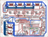
Это - схема, вид сверху. Если не уверен, как повернута плата, всегда смотри на схему. Обозначения совпадают со списком деталей.
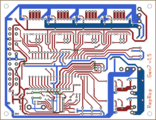
Это - схема, вид снизу. Запомни что MCP2200 находится с этой стороны.
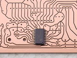
Это изображение показывает как разместить MCP2200. Точка отмечает ножку 1 - это нижний правый угол. Для подсказок по пайке смотри инструкцию по EB-USB-B.
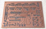
Для достижения наилучшего качества пайки, подготовь все оставшиеся точки пайки перед установкой компонентов. На снимке плата GEN7 v1.4.


- Начни с 9 мостов из провода. На схеме они в виде зеленых дорожек. Дорожки внутри кнопки reset - это не мосты (эти соединения создает сама кнопка reset).
| 10 Ω | 560 Ω | 1 kΩ | 4.7 kΩ | 10 kΩ |
| коричневый-черный-черный | зеленый-синий-коричневый | коричневый-черный-красный | желтый-фиолетовый-красный | коричневый-черный-оранжевый |
- D1 и D2 - диоды, так что соблюдай полярность. Диод имеет белую полоску, которая должна быть ближе к краю платы.
- L1 выглядит как толстый резистор, но на самом деле это катушка индуктивности.
- LEDы - тоже диоды, полярность имеет значение. Длинная ножка значит (+), идет в отверстие со знаком + на схеме.
- Электролитические конденсаторы тоже имеют полярность. Белая полоска обозначает (-), а длинная ножка обозначает (+).
- Неплохо было бы вставить драйверы шаговых двигателей в свои гребенки, чтобы обеспечить правильное расположение.
- Не забудь о полярности дисковых коннекторов питания: скошенные края указывают направление для установки.
- Оснастка ATX24 указывает в центр платы.
Спустя некоторое время, у тебя получится что-то наподобие этого:

Как ты видишь, автор решил использовать Molex KK156 разъем для экструдера и горячего стола. Другие могут выбрать крепление шурупом, или оба крепления сразу.
Ни MOSFET (МОП-транзисторы), ни ATmega еще не установлены. Мы вернемся к ним позже.
Также есть два ряда отверстий до и после ATmega'и, которые остаются пустыми. Это место для платы расширения. Паять сюда гребенку стоит только лишь если собираешься подключать плату расширения, ну или несколько плат (одна на другой).
Setup
These steps show how to get from a soldered mainboard to a working one.
Possible Power Sources
Плату "Generation 7 Electronics" можно подключить к блоку питания двумя способами.

Вариант 1

Во первых, рекомендуем использовать для обеспечения питанием обычный блок питания от компьютера ATX на 24 пина. Он обеспечит током все компоненты.
One point to take care of is, PC PSUs have two or three strings with several Disk Power connectors on each string. Each of the strings can supply about 10 Ampéres only, so make sure you plug in only one connector of each string into Gen7's headers if you use a heated bed or some other high-current device.
ATmega может работать с выключенным блоком питания ( в режиме ожидания), так что не удивляйтесь что блок питания в начале работы выключен. Он запуститься только после "G кода-команды" запуска.
Примечание: Разъём блока питания есть на 24 контакт и на 20 контактов. Не переживайте если у Вас такой разъём блока питания, он тоже подойдет и ничего паять не нужно, просто вставляем его в тот же разъем что и 24-контактный. Он вставится только в одной положение:

Вариант 2
Плата подключается к блоку питания фишками на 5 Вольт и 12 Вольт. В этом случае питание на плату и двигатели идет постоянно и программно подача питания не контролируется
Установка перемычки питания
Как подключите питание, Вы должны поставить перемычку, согласно выбранному способу питания.

В правом нижнем углу вы найдете "пины" для перемычек.
- ATX20/ATX24: поставить перемычку ближе к разъемы ATX.
- Disk Power: поставить перемычку чуть ниже.
Ставить можно и нужно только 1 перемычку, согласно способу подключения.
Проверка блока питания
После того, как поставили перемычку, перед монтажом драйверов и микроконтроллера нужно проверить плату на предмет коротких замыканий.

The picture shows a Gen7 v1.4. In addition to the shown voltages, you'll recognize 5 V on pin 14 and up to 1 V on pin 15. These are RxD and TxD of the already running MCP2200.
- Red: power supply inserted according to any option. In case of an Option 1, PSU not yet activated.
- Blue: as above, with PSU activated or power supply according to Option 2.
Note: in the picture, no 5 V selection jumper is inserted, but you need the right one here.
Checks:
- No smoke? Great.
- The yellow LED in the lower right corner is lighted? Even better.
- If you've chosen Option 1, short the wire bridge with the top right pin of the ATmega socket like the dashed green line in the picture. This should activate the power supply.
- At the same time, the green LED in the lower right corner should go on as well.
- If you have a voltage meter, measure the voltages shown in the picture. Dots mean wire bridges, arrows mean pins.
- Also, check each of the pins of the ATmega socket, none of them should have more than 0.5 volts, except those marked to have 5 V. On the ATmega socket, this is pin 9, 10, 21, 30, 39 and 40 (counter-clockwise, starting at the lower left).
- Check the pins in the lower row of the Pololus. Neither of the unmarked ones should exceed 0.5 volts as well.
With everything within the limits, you can pretty safely assume to not blow up the expensive parts when inserting them.
Insert Semiconductors
Now, with some safety tests done, it's a good time to insert semiconductors.

Note: the picture shows the Gen7_v1.4.1 board, the Gen7 AVR 1.5 board has the same MOSFET's IRLB 8743
- Disconnect the power supply entirely.
- Both MOSFETs are marked with IRLB 8743
- Solder both MOSFETs with the flat side towards the center of the board into their place. Use sufficient solder, as high currents are flowing here.
- Insert the ATmega into it's socket. Like every integrated circuit with such a housing, there's a groove on one of the ends of the black box. This groove shows towards the MOSFET side of the board, the non-grooved end is close to the ATX24 header. Done right, you can read the text on the housing from the ATX24 header side correctly.
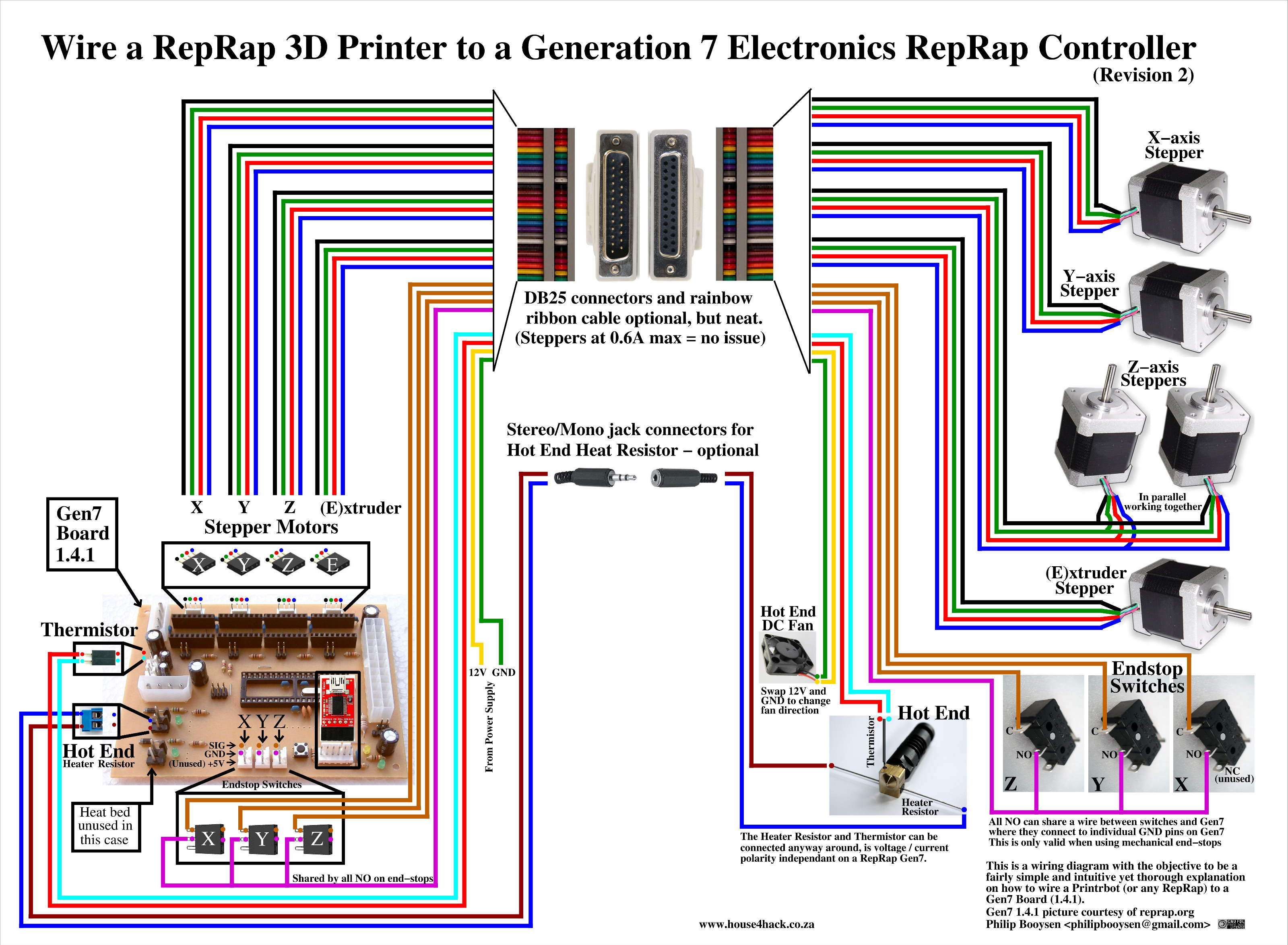
Wiring to your Reprap Printer
Here is a nice diagram indicating one wiring solution.
Objectives
- Depict how to wire a RepRap 3D Printer (eg. Printrbot) to a Gen7 Board
- Diagram to be fairly simple and intuitive yet a thorough explanation
- Objective was not to create a PCB schematic but just a simple to understand diagram
Disclaimer
- Agree that your mileage might vary in how you implement the wiring,
- Connectors and wire color, type, gauge and any other aspects of wiring might differ for your case
- This is merely an attempt at documenting how to wire up a RepRap to a Gen7 1.4.1. It should work as a guide for Gen7 1.5 too.
- If something blows up, you stay responsible (:
The Diagram
The below diagram explains how to wire a RepRap 3D Printer to a Gen7 Board 1.4.1. Should also work as a guide for Gen7 1.5.
It is imperative that you view or download the original file as it is 7.5 MegaPixels and the diagram was designed with some fine detail and possible zoom and pan in mind.

Diagram was created using xfig (free and open source vector graphics editor) and is licensed under the GNU Free Documentation License (www.gnu.org/licenses/fdl.html) - Philip Booysen - House4Hack.
Serial connection on Mac OS X
First of all, if you run OS X v10.7 or later, you shouldn't have issues. Plugging the Gen7 into an USB port should cause a new device showing up in /dev, which provides the required serial port. Just like in Linux.
For earlier Macs, there's the mcp2200-forwarder tool. A binary for PowerPC Macs is in the release documents folder on Github. Download and place it in /usr/bin, then run it like this:
mcp2200-forwarder-macosx-ppc -b 115200 -l /tmp/ACM0
The -b flag must match the baud rate of your Gen7. Keeping this tool running you can fire up Pronterface and connect to /tmp/ACM0. That's it! You can plug and unplug the Gen7 while the tool is running, put the Mac to sleep and wake it, no need to ever restart it. If you think it messed up, pressing reset on the Gen7 should be sufficient.
In case you have an early i386-Mac, you have to compile the tool. Pretty simple with Xcode installed. For this, and more details, see its README.
Programming the MCP2200
While the MCP2200 will work without any configuration, the Rx/Tx pins that control the LEDs are disabled by default. There's a MCP2200 Configuration Utility which allows advanced configuration, including enabling the blinking of the Rx/Tx indicators (see also these two forum postings). This tool also allows changing the general purpose I/O (GPIO) pins of the chip. An available library can be used to write custom windows applications using this. Not very helpful in the Linux world, the tool doesn't run using Wine.
Additionally, while configuring the MCP2200 ensure the "Enable CTS/RTS Pins" option remains unchecked. This option enables control of these pins internally by the chip and disables control by the OS. Enabling it will cause the arduino software to be unable to reset the chip properly while programming and may cause unexpected resets if the receive buffer manages to fill up.
An attempt to hack the chip using open source tools is usbio. If you want to dive in even further, the MCP2200 is a custom-programmed PIC18F14k50 and can be reprogrammed. :-)
Troubleshooting the MCP2200
Starting at this post in the forum it's described how the MCP2200 doesn't work on some Windows 64-bit versions. So far no known solution.
Additional info from Rezer, he runs this chip successfully with Win7 64-bit:
- Oh, and I checked the mcp2200 driver version on my windows 7 64 bit machine...it was 1.2 (5.1.2600.3), and I uninstalled it and plugged the board back in. It automagically pulled 1.3 (5.1.2600.7) from windows update and still works fine *shrug*. I have UAC turned off on my machine, unsure if that would make a difference.
A first test is to check wether the MCP2200 appears as serial device in the OS of the host PC. If this doesn't happen, either the MCP2200 its self or the cabling to it desn't work or the OS has no driver to serve it. This should work with no ATmega inserted, too.
A second test for the MCP2200 is to take out the ATmega (or do this test before inserting it), then plug a bridge (bent piece of wire) between pin 14 and 15 (RxD and TxD of UART0) into the ATmega socket. Then connect with a serial terminal and type something. Even without local echo enabled in the serial terminal, you should see what you type. With local echo enabled you'd see every character echo'd twice. This means, characters are sent out to the ATmega, into the bridge and immediately back. All the wiring up to the ATmega socket works!
If you are Linux user, the MCP2200's driver is include in kernel. On some distributions it may need activation. To do so, enter
sudo modprobe cdc-acm
You can insert this command without "sudo" in /etc/modules to activate it on boot.
If you are using an older version of Pronterface, sometimes the board won't connect to it. You need to modify the file named printcore.py line 157: time.sleep(0.25) must be time.sleep(5).
Thank you to Andol for figuring the latter two fixes.
Bootloader
If you bought your ATmega with one of the Gen7 kits, the bootloader should have already been uploaded and you can skip this section. Any other bootloader, like the one used for the Sanguino, RAMPS, Sanguinololu or whatever is also fine.
If you bought an factory fresh ATmega, e.g. from a general electronics supplier, the ATmega will be without bootloader. How to change that is described in the Bootloader Upload section of the Gen7 Arduino IDE Support package. You'll find the required binaries there, too.
If you're in doubt, just continue with the setup. A missing bootloader will result in a timeout error when attempting to upload a firmware.
Firmware
In principle, you can run any of the ATmega compatible RepRap Firmwares on this board. Adjust the I/O pin layout, adjust compile time options for no secondary board/no RS485 and proceed. Just like Gen2, RAMPS, Sanguinololu or similar electronics.
There's also no Gen7-specific choice for the slicer or the G-code sending application. Use what you prefer or what owners of other electronics use.
Pinout
The pinout of ATMega644/ATMega1284 hasn't changed since version 1.4, so if you have your firmware configured for this version, no changes are needed. For example, if you are using Teacup firmware, you can use config.gen7-v1.4.h configuration file.
The following should help to configure other firmwares:
                 +--------\/--------+
INT8 (D 0) PB0  1|> Xmin  Temp_Bed {|40 PA0 (AI 0 / D31)
INT1 (D 1) PB1  2|> Ymin  Temp_Ext {|39 PA1 (AI 1 / D30)
INT2 (D 2) PB2  3|> Zmin     Xstep >|38 PA2 (AI 2 / D29)
 PWM (D 3) PB3  4|< Heat_Bed Xdir  >|37 PA3 (AI 3 / D28)
 PWM (D 4) PB4  5|< Heat_Ext Ystep >|36 PA4 (AI 4 / D27)
MOSI (D 5) PB5  6|           Ydir  >|35 PA5 (AI 5 / D26)
MIS0 (D 6) PB6  7|           MotEn >|34 PA6 (AI 6 / D25)
 SCK (D 7) PB7  8|                  |33 PA7 (AI 7 / D24)
           RST  9|                  |32 AREF
           VCC 10|                  |31 GND
           GND 11|                  |30 AVCC
         XTAL2 12|           Zstep >|29 PC7 (D 23)
         XTAL1 13|           Zdir  >|28 PC6 (D 22)
RX0 (D 8)  PD0 14|                  |27 PC5 (D 21) TDI
TX0 (D 9)  PD1 15|                  |26 PC4 (D 20) TDO
RX1 (D 10) PD2 16|           Estep >|25 PC3 (D 19) TMS
TX1 (D 11) PD3 17|           Edir  >|24 PC2 (D 18) TCK
PWM (D 12) PD4 18|                  |23 PC1 (D 17) SDA
PWM (D 13) PD5 19|                  |22 PC0 (D 16) SCL
PWM (D 14) PD6 20|           PwrEn >|21 PD7 (D 15) PWM
                 +------------------+
Modifications
Here are modification which fix things which either customize something or are a peek into the next version of Gen7.
Compatibility with early DRV8825 based Pololus
These early DRV8825-based "Pololus" lack a pullup on the Sleep pin. This can be fixed with an additional track like this:

This light blue line is an additional track which can be done with a simple solder blob on the real board. It pulls Reset & Sleep always up, a feature missing on these stepper drivers. This modification is required for each of the four stepper drivers and has no drawbacks when using A4983 or A4988 based Pololus. It'll go into the next Gen7 release.
That said, Pololu has replaced these early ones already with a version which fixes exactly that: http://www.pololu.com/catalog/product/2133
Page creation in progress. For now, see Gen7_ExtensionBoard_USB_B_1.0 for the new USB adapter and Gen7 Board 1.4.1 for the remaining.
User:TV productions assembly pictures


File:Gen7 Board 1.5 Assembly 22.jpeg
File:Gen7 Board 1.5 Assembly 23.jpeg
File:Gen7 Board 1.5 Assembly 24.jpeg
File:Gen7 Board 1.5 Assembly 25.jpeg
File:Gen7 Board 1.5 Assembly 26.jpeg
File:Gen7 Board 1.5 Assembly 27.jpeg
File:Gen7 Board 1.5 Assembly 28.jpeg
File:Gen7 Board 1.5 Assembly 29.jpeg
File:Gen7 Board 1.5 Assembly 30.jpeg
File:Gen7 Board 1.5 Assembly 31.jpeg