Extruder/Mendel
Mechanical: Overview | Mendel solid model files | Procurement | Preparation of materials | Assembly notes | Extruder | X-axis | Z-axis | Y-axis | Circuit boards | Frame | Squaring the axes
This page describes the standard extruder for RepRap Mendel. There are experimental (and so more advanced but less tested) alternatives here and here that you may care to look at too.
Mendel uses a thermoplast extruder based on RepRap's Thermoplast Extruder Version 2.0. The principle is exactly the same, but a redesign has condensed the RP parts into one component (click here for instructions on how to get hold of RepRapped parts). The rest of this page will deal with the new assembly only.
BOM
Assembly qty: 1
| Name | Qty/assembly | Total Qty | Type |
| Thermal-barrier and nozzle | 1 | 1 | Assembly |
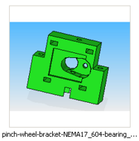
| pinch-wheel-bracket-NEMA17_604-bearing_1off.par | 1 | 1 | RP |
| m3-capx25.par | 4 | 4 | Fastener |
| m3-washer.par | 4 | 4 | Fastener |
| 624-bearing.par | 1 | 1 | Bearing |
| m4-nylock.par | 1 | 1 | Fastener |
| m4-washer.par | 5 | 5 | Fastener |
| m4x16-cap.par | 1 | 1 | Fastener |
| m4x40-cap.par | 2 | 2 | Fastener |
| stepper-motor-nema17-fl42sth47-1684A-01.par | 1 | 1 | Motor |
| stripboard | 1 | 1 | Electronics |
| ~4cm heatshrink | 1 | 1 | Electronics |
| 6-ohm length fibreglass-insulated nichrome wire | 1 | 1 | Electronics |
| 200mm 4-way ribbon cable | 1 | 1 | Electronics |
| bootlace ferrule or crimp | 2 | 2 | Electronics |
| Thermistor | 1 | 1 | Electronics |
| 4-way Pin-Header | 2 | 2 | Electronics |
Thermal-barrier and nozzle
These are the only parts of RepRap that need to be machined. The DXF files for these drawings created by the free QCad CAD system are in the folder mendel/mechanics/solid-models/extruders/pinch-wheel of your RepRap download.
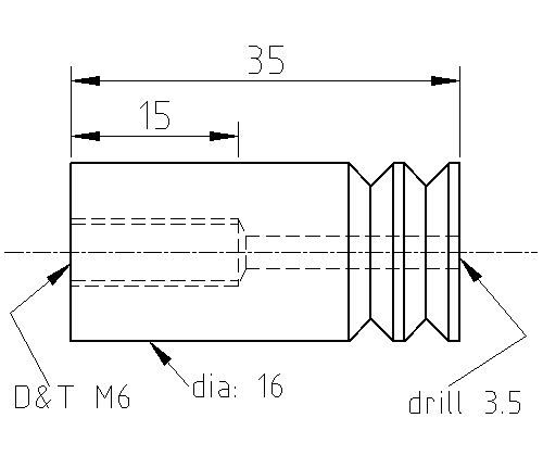
Here are the dimensions of the thermal barrier. It is made from 16mm diameter PTFE rod.
If you don't have access to a lathe, you can try this method
Start by facing off the ends. Then touch a centre drill on, and follow it right through with a 3.5 mm drill. Use a woodpecker cycle to clear the swarf.
Next mark 15 mm from the tip of a 5 mm drill with a fine felt-tipped pen (the tapping drill for M6), and drill to your mark.
Now mark 15 mm from the end of an M6 bottoming tap, turn off the power to your lathe, and put the tap in the tail stock. Turning the chuck by hand, cut the M6 thread to your mark.
The valleys cut in the end of the thermal barrier need to cover slightly less than the top 10mm of its length. They are just there to key into some glue, and so don't need to be very precise, nor do you need exactly two. I have made them perfectly well by putting the cylinder in the chuck of a Black and Decker drill and then just running a triangular file against it.
This is the barrel. It is made from M6-threaded brass rod (or an M6 brass screw with the head cut off).
This next step is a lot easier if done with a lathe. Though if you don't have access to one, you can drill the rod all the way through with a 3.5mm dia drill on a drill press and vice, then drill a 0.5mm dia hole into a dome nut, be sure you use a centre drill first to make sure everything stays concentric/true.
Start by facing off the ends. Then touch a very small centre drill on. Drill the 0.5 mm hole for the nozzle about 3 mm deep. Go slowly and carefully, and withdraw the drill frequently to clear the swarf. An 0.5 mm drill is very fragile.
Next turn and clamp the cross-slide at 45o and turn the connical end. Take it far enough to get rid of the mark left by the centre drill and to take away a bit of the 0.5 mm hole. You will probably find that the 0.5 mm hole closes up - clear it by hand with the 0.5 mm drill held in a small hand chuck.
Holding both in your hands, offer up a 3.5 mm drill beside the brass. Get its pointed end about 2 mm from the tip of the cone you turned, and move it about so that it is as near the tip as possible while still leaving a bit of brass to hold the tip on. Mark where the other end of the brass comes with the felt-tipped pen, and once more drill to your mark. The 0.5 mm hole you made should meet up with the 3.5 mm hole, but you may again need to clear it using the 0.5 mm drill by hand.
RP parts
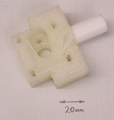
Cablear y pegar
La barrera térmica PTFE se debe pegar a la pieza reprapeada con pegamento epoxy. Cualquier epoxy fuerte servirá; El Araldite rápido es bueno.
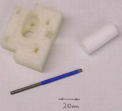
Necesitarás una varilla de 3.5 mm de diámetro para dejar los agujeros para excluir el pegamento y conseguir que todo quede centrado. Yo no tenía una varilla de 3.5 mm, así que hice una con una varilla de 3 mm y algo de cinta Scotch (la azul en la imagen).
Pon una pequeñísima cantidad de silicona gris en la varilla para evitar que el pegamento se atasque, y une las piezas. Monta algunos bloques de forma que puedas mantener el ensamblaje, con la barrera térmica apuntado hacia arriba en posición vertical para que el pegamento se seque.
Revuelve el pegamento, retira la barrera térmica, aplica el pegamento a las paredes de la pieza reprapeada con un pequeño destornillador. Ten cuidado de no pegar el plano del fondo del agujero.
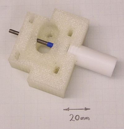
Aplica el pegamento alrededor de los valles de la barrera térmica, y ensambla las piezas. Si retuerces la barrera térmica alrededor de la varilla que la atraviesa ayudarás a que se extienda el pegamento. Añade más pegamento si quedan huecos - verás que si lo añades al agujero en el lateral, y luego retuerces la barrera térmica un poco, arrastrarás el pegamento y harás que se desplace entre las piezas.
Pon un trozo de cinta sobre el agujero en el lateral.
Mantén el dispositivo con la barrera térmica apuntado hacia arriba para que el pegamento se seque.
Cuando el pegamento esté gomoso, pero no completamente seco, retira la varilla. Utiliza una broca de 3.5 mm para limpiar a mano cualquier resto de pegamento que pudiera quedar.
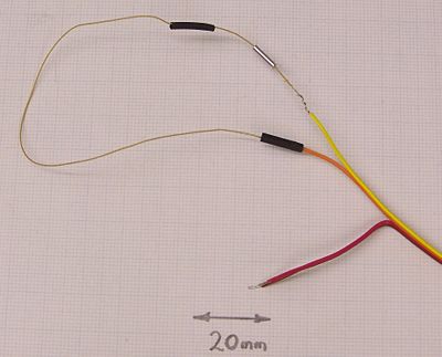
Corta un alambre de nicrom(en inglés) (con aislante de fibra de vidrio) de 6-ohm de longitud y pela los extremos.
Corta unos 200 mm de longitud del cable de cinta de 4 hilos y pélalos en unos de sus extremos. Pela una pareja unos 15 mm y la otra pareja unos 5 mm.
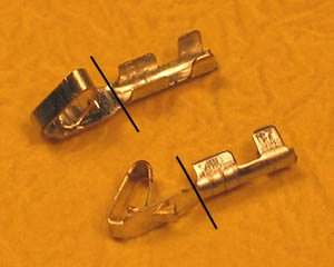
Debajo hay otro método en lugar de usar cordones de férula, que pueden ser difíciles de encontrar, y es solo un ejemplo de cuero. Corta el extremo de la cabeza de cuero marcada en negro.
Enrolla uno de los extremos de los cables largos hacia un extremo del alambre de nicrom(en inglés), y aplasta un cordón de férula sobre el para asegurarlo (también se puede modificar cualquier otro cuero conector de cabezal en lugar de la férula). No deberías soldar las conexiones de alambre de nicrom(en inglés) porque:
- La soldadura no derrite el alambre de nicrom(en inglés); puedes usar soldaduras de alta temperatura, pero necesitarás una soldadura de hierro muy caliente, y
- El alambre de nicrom(en inglés) se pondrá muy caliente durante su uso normal y puede fallar ocasionalmente.
Pon manguitos termo-retráctiles sobre el cordón de férula o cuero.
Ahora has con el otro cable lo mismo. Piensa cuidadosamente en que orden y que orientación pones el cordón de férula y los manguitos antes de enrollar los cables...
Envuelve cuidadosamente unos pocos centímetros de cinta de fontanero PTFE alrededor del cañón de latón donde se atornillará en el cilindro PTFE para mejorar el agarre. Atornilla fuertemente el cañón en el PTFE, pero no tan fuerte como para dañar el PTFE - recuerda que es frágil.
Corta unos 20 mm de cinta Kapton(en inglés) de 10mm de ancho, y pégalo al lateral de la mesa de forma que puedas cogerlo fácilmente.
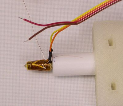
Wind the nichrome wire onto the brass in the valleys of the threads. Start at the PTFE end, run a length straight towards the tip, then wind round and round back to the PTFE covering the straight piece you just laid.
Wrap the Kapton tape on to hold the coils you've made.
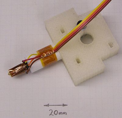
Cut a couple of 5mm lengths of Kapton tape and fold them over the leads to the temperature-sensor. Then use more Kapton tape to attach the sensor near the tip of the nozzle. Make sure the sensor itself is touching the brass of the barrel.
Cut two short lengths of heatshrink and put them on the other pair of ribbon cable wires. Solder those wires to the temperature sensor leads, and then put the heatshrink over the joints. Have the leads sticking out sideways outside the wound tape to keep these joints cool.
Wind more layers of Kapton tape on to secure everything and to give a bit of thermal insulation.
Attach the ribbon cable to the PTFE with a final length of Kapton tape.
Assembly
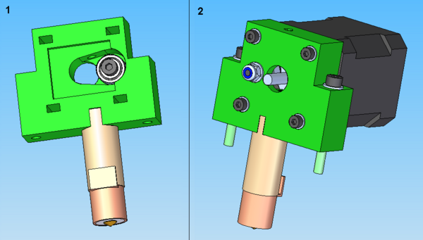
- Secure bearing using M4x16 cap, and glue nozzle assembly into pinch wheel bracket. Follow Thermoplast Extruder Version 2.0 documentation for gluing procedure. Note images below show the prior version of the heater which had a wide cover over it.
- Loosely attach motor. Motor wires should run upwards. Set distance between motor shaft and bearing to 2.5 mm – use the round shank of a 2.5 mm drill bit poked down the filament hole as a spacer. Lock motor into position. Load M4x40 caps for ready for next step.
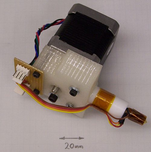
A neat way to make the electrical connections is to cut a piece of stripboard the same width as the top of the reprapped part of the extruder. Put two 4-way pin headers on it and use one for the motor connections, and one for the heater and temperature sensor.
Secure the stripboard using the top two motor-holding screws. Use no washers, otherwise the threads won't be long enough to attach the motor securely.
For the bottom two screws, you can use an M4 washer under an M3 one as shown - this will help spread the load on the reprapped part and reduce distortion.
Back to Mendel mechanical construction root.
