Ohm/How to build an OHM
This page is a development stub. Please enhance this page by adding information, cad files, nice big images, and well structured data!
Contents
- 1 Introduction
- 2 Mechanical Construction
- 3 Electrical Construction
Introduction
The Open Hybrid Mendel (OHM) has several advantages over the generic Mendel model. Mainly, it is more flexible. The extruder carriage and printing board are designed to easily pop off the machine without unscrewing any parts.
All STL files mentioned in this article are referring to, and can be downloaded from the OHM Parts section.
Mechanical Construction
Frame
Frame Triangles
Parts
To make the frame triangles, 6 frame vertices, 2 bar clamps and 6 threaded bolts are needed.


Assembly
(Assembly guide. Delete this note when section is finished)
Tips
When you assemble the frame triangles, it will be easier if you assemble the two top vertices the last. To insert the rod into the vertices, you can tie two nuts tight together and then use a wrench to screw in the rod.
Connecting the Triangles
Parts
(Parts needed for assembly. Delete this note when section is finished)
Assembly
(Assembly guide. Delete this note when section is finished)
Tips
(Extra tips to help assemble. Delete this note when section is finished)
View of unfinished Y-axis
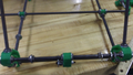
View of unfinished Y-axis
Finished Frame


Z Drive System
Z-Axis Motor Mounts
Parts
(Parts needed for assembly. Delete this note when section is finished)
Assembly
(Assembly guide. Delete this note when section is finished)
Tips
(Extra tips to help assemble. Delete this note when section is finished)
Z-Bar assembly
Parts
(Parts needed for assembly. Delete this note when section is finished)
Assembly
(Assembly guide. Delete this note when section is finished)
Tips
Assembly of Z-axis can be started from sticking everything together in one rod. Settling all the parts (including the two top vertices for the frame triangle) on Z axis and connecting them with rod at one side, then insert the rod for the other side.
X-Z Assembly
X-Axis Motor Mounts
Parts
(Parts needed for assembly. Delete this note when section is finished)
Assembly
(Assembly guide. Delete this note when section is finished)
Tips
(Extra tips to help assemble. Delete this note when section is finished)
X-Axis Vertical Bearing
See Mendel X-Axis for further information.
Parts
Total # of assemblies: 1
| Name | Qty/assembly | Total Qty | Type |
| z-flag.par | 1 | 1 | Thin sheet |
| x-axis-side-plate-nut-jig_2off | 1 | 1 | RP |
| x-bar-clamp-m4_4off | 2 | 2 | RP |
| x-vert-drive-nut-trap_4off | 2 | 2 | RP |
| x-vert-drive-side-plate-180-end_2off | 2 | 2 | RP |
| m4-nut | 4 | 4 | Fastener |
| m4-nylock | 4 | 4 | Fastener |
| m4-washer | 16 | 16 | Fastener |
| m4x40-cap | 8 | 8 | Fastener |
| m8-nut | 1 | 1 | Fastener |
Reprapped parts

Assembly

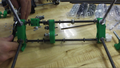
First, assemble the x-vert-drive-nut-trap_4off. To do this, you need a lighter, four m4 nuts and a m4x40-cap. Place an m4 Nut on the end of the m4x40-cap and heat with the lighter. Caution: Do not heat for too long or the m4x40-cap will become very hot.

Push the heated nut into one of the hexagonal holes in the x-vert-drive-nut-trap_4off. Repeat for all four nuts.

Screw x-vert-drive-side-plate-180-end_2off and x-bar-clamp-m4_4offtogether using m4x40-cap and washers. Do not screw them all the way in.

Screw x-vert-drive-nut-trap_4off into x-vert-drive-side-plate-180-end_2off using a diagonal pattern. Remember to use washers. Do not screw them all the way in.


Repeat previous steps to create other half. Make sure that you place the screws diagonally in a way that they do not interact with the other screws.

Place the x-vert-drive-nut-trap_4off in between the bottom half of the two sides and line up screws. Screw in the M4 screws until they sit in the nuts and are firmly in place. This could take some adjustment.
Place an M8 nut in between the two trap sides. Then screw the upper screw together. Tighten all screws in steps.


Tips
- In some cases, though it is not necessary, it may help if you drill out the holes before assembling.
- To help align the screw holes, place on screw in, clamp the parts, and drill the rest of the holes.
Assembling the X-Axis
Parts
(Parts needed for assembly. Delete this note when section is finished)
Assembly
(Assembly guide. Delete this note when section is finished)
Tips
(Extra tips to help assemble. Delete this note when section is finished)
Connecting the X-Axis to the Z-Axis
Parts
(Parts needed for assembly. Delete this note when section is finished)
Assembly
(Assembly guide. Delete this note when section is finished)
Tips
(Extra tips to help assemble. Delete this note when section is finished)
Z and X axes Endstops
Parts
(Parts needed for assembly. Delete this note when section is finished)
Assembly
(Assembly guide. Delete this note when section is finished)
Tips
(Extra tips to help assemble. Delete this note when section is finished)
OpenY Axis
Y-axis Guide Bars
Parts
(Parts needed for assembly. Delete this note when section is finished)
Assembly
(Assembly guide. Delete this note when section is finished)
Tips
(Extra tips to help assemble. Delete this note when section is finished)
OpenY Assembly
Parts
(Parts needed for assembly. Delete this note when section is finished)
Assembly
(Assembly guide. Delete this note when section is finished)
Tips
(Extra tips to help assemble. Delete this note when section is finished)
Print Bed
Parts
(Parts needed for assembly. Delete this note when section is finished)
Assembly
(Assembly guide. Delete this note when section is finished)
Tips
(Extra tips to help assemble. Delete this note when section is finished)
Motors, Belts and Endstops
Parts
(Parts needed for assembly. Delete this note when section is finished)
Assembly
(Assembly guide. Delete this note when section is finished)
Tips
(Extra tips to help assemble. Delete this note when section is finished)
Extruder
Carriage
Parts
(Parts needed for assembly. Delete this note when section is finished)
Assembly
(Assembly guide. Delete this note when section is finished)
Tips
(Extra tips to help assemble. Delete this note when section is finished)
Motor Mount
Parts
(Parts needed for assembly. Delete this note when section is finished)
Assembly
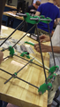
(Assembly guide. Delete this note when section is finished) This unfinished part includes the main driven gear, idler and lastly the main section.
Extruder part work in progress

Tips
(Extra tips to help assemble. Delete this note when section is finished)
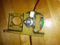
Hot Tip + Electronics
Parts
(Parts needed for assembly. Delete this note when section is finished)
Assembly
(Assembly guide. Delete this note when section is finished)
Tips
(Extra tips to help assemble. Delete this note when section is finished)
Spool
Spool Assembly
Parts
(Parts needed for assembly. Delete this note when section is finished)
Assembly
(Assembly guide. Delete this note when section is finished)
Tips
(Extra tips to help assemble. Delete this note when section is finished)
Spool Mount
Parts
(Parts needed for assembly. Delete this note when section is finished)
Assembly
(Assembly guide. Delete this note when section is finished)
Tips
(Extra tips to help assemble. Delete this note when section is finished)
Electrical Construction
RAMPS
Motherboard
RAMPS 1.4 is used as our mother board.


Soldering Tip
It is better to solder from the center of the mother board to the edge. If you solder the pins on the edge first, they will make it difficult to solder the pins in the center.

Top pins
Solder 1 1x6, 6 1x4, and 7 2x3 pin headers on top of the board. The long post should be standing up to take a connector.
Solder one leg on each one to tack them into place. Then re-heat the joint and push on the component until it is perfectly situated.
Then you'll want to solder the rest of the leads. You will get burnt if you touch the other side of the pin you are soldering.
