FoldaRap1 Build Manual
|
English • العربية • български • català • čeština • Deutsch • Ελληνικά • español • فارسی • français • hrvatski • magyar • italiano • română • 日本語 • 한국어 • lietuvių • Nederlands • norsk • polski • português • русский • Türkçe • українська • 中文(中国大陆) • 中文(台灣) • עברית • azərbaycanca • |


Tools required
- 1,5 mm hexagonal wrench (for the pulleys grub screw)
- 2 mm hexagonal wrench (for M3 counterksunk bolts and pneumatic fittings "MA-12-03-M5")
- 2,5 mm hexagonal wrench (for normal M3 cap-head bolts and the rounded M4 bolts used for the frame)
- little flat screwdriver (1,5mm) (for the board's screw terminals)
- Philips (PH2) or flat screwdriver (3mm) (for the psu's screw terminals)
You may need also :
- a 5,5mm flat spanner or a small pliers (for m3 nuts)
- something to cut wires, and strip them (knife, automatic striper, etc.)
- a lighter for the heat-shrink sleeves
- soldering iron (to eventually solder the endstops)
- small files (round, flat) to eventually ream the printed parts
- a glue gun (gluing the endstop on the printed part is easier/quicker than using bolts)
- a multimeter (to set the drivers current)
Contents
BOM
Hardware

5  20x20mm beam 6mm slot 200mm - Motedis or see Aluminium profile
6  20x20mm beam 6mm slot 300mm
50 M4 T-nut for 6mm slot - Motedis
(=31€)
50 m4x8 round head bolt - Fix'n Vis Round Head Bolt
2  m3x4 / Hotend-heatsink(2) Fix'n Vis Bolts
15 m3x8 bolt / Z-motors (4), Y-motor (3), X-end-idler (2), psu (2), male plug (2), board-mount (2)
2  m3x10 bolt / hotend (2)
6  m3x12 bolt / X-idler (1), extruder (3), Y-belt-clamp (2)
4  m3x16 bolt / X-motor (3), extruder-fan (1)
7  m3x20 bolt / X-carriage (3), hinges (2), Y-idler (1), extruder (1)
3  m3x30 countersunk bolt / bed (3)
2  m3x35 / extruder (2)
19 m3 nut / hinges (2), X-carriage (3), X-idler (2), extruder-fan (1), bed (3), Y-belt-clamp (2), extruder (2), plug (2), psu (2) - Fix'n Vis Nuts
3  m3 nylock nut / bed leveling (3) nylock nut
5  m5 nut / extruder pneumatic fitting (1), Z-rod (4) (for the Z nylon nuts can be slightly better)
11 m3 washer / X-motor (3), X-idler (2), extruder (2), Y-idler (2), Y-belt-clamp (2) - Fix'n Vis washer
2  230mm threaded rod m5 - Fix'n Vis
(=9€)
2  extruder spring - RS751483 or see Springs
3  bed spring - RS 751455 or RS 751607
1m spiral wrapping band for tidying the wires - RS227874
7  faston ferule - Radiospare to crimp the cable for the plug and the switch
(=15€)
2  polymer coupling - See this thread (ebay / emakershop)
6  linear bearing, LM6UU or if you can Igus RJMP-01-06 - See Bearing
4  300mm smooth rod 6mm - (can be salvaged from usual scanners and printers) or see Smooth rod
4  603zz bearings / X-idler (1), Y-idler (2), extruder-idler (1)  - See Bearing
1  600mm T2.5 belt 5-6mm wide - RepRapWorld or see Belts_and_Pulleys
1  700mm T2.5 belt 5-6mm wide
2  T2.5 pulleys - Paoparts or see Belts_and_Pulleys
1  PTFE Tubing for bowden extruder (2mm inner diam. and 3mm outer), 300mm long - See Bowden
2  Pneumatic fittings for 3mm tubing, with M5 thread - See Bowden or emakershop / I'm using the MA12-03-M5 but others can work
1  direct drive gear - Maritime-models (see Drive-gear)
1  bed plate 4mm thick
1  roll of kapton - See Kapton Tape#Vendors
20-30 zip-ties
Electronic
5 nema14 stepper motors - [2]
3 miniature microswitch endstop 20mm - [3]
1 standard male plug IEC C13 C14 - RS 5392045
1 standard female cable - EU/C13 - UK RS6266739 / US RS7316163
1 big blue switch - RS 5287858
1 RepRappro Hotend - emaker
1 40x40mm heatsink - RS 6744769 to make a more compact hotend
1-2 small fan (40 x 40 x 10 mm), for the hotend (can be bought with one) and the extruder motor - RepRapWorld or see Fan
1 100k thermistors - Mouser
0.6 m of 18AWG wire (200mm red, 200m black, 150mm green) for the switch/plug/psu - Read also WiresAndConnectors
10 m of 26AWG (3.6m red, 3.2m green, 2.0m blue) for the sensors and fans
1 Minitronic board [4]
1 USB cable A to B [5]
1 12V power supply : 5A or 10A or [6] (for heated bed)
or
1 Melzi board [7], [8]
1 usb to mini-usb cable - [9]
1 12V power supply : 5A or 10A or [10] (for heated bed)
or
1 Azteeg_X1 board - [11] + 4 drivers
1 usb to mini-usb cable - [12]
1 12V power supply : 10A
or
1 Rumba + 6 stepper drivers
1 usb to mini-usb cable - [13]
1 12V power supply : 20A (RS 7066316 100*150*35mm)
Laser cut parts


See the github repo and eMakerShop, you can have them from Ponoko too
1 electronic under-plate 3-4mm thick
1 bed-plate 4-6mm thick (acrylic or aluminium)
1 Y-carriage
1 reprap.org plate 160x20mm, 2-4mm thick (+2 T-nut and M4x8) - optional but make a nice reference to the wiki :)
These parts can also be made by hand with simple tools.

Printed parts (total : 21)
See also the github repo
foot front left
foot front right
foot rear left
foot rear right
hinge-inner left
hinge-inner right
hinge-outer left
hinge-outer right
z-motor-bracket left
z-motor-bracket right
z-top left
z-top right
y-motor
y-idler
y-belt clamp
x-end-motor
x-end-idler
x-carriage
extruder-idler
board mount (x2)
Other
Heated-Bed
For the aluminium heated bed add :
1 aluminium bed plate (4mm thick)
1 100k thermistors - Mouser
60cm of 26 AWG wire (blue)
2 ferule 0,5mm²
1 peltier element 12708 (40x40mm is enough) - ebay
General tips
- Read the whole manual once or twice before starting, to get an overview of the build
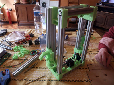
- Basically we have a main frame and several sub-assemblies, some can be done in parallel : gather your friends and establish a record for minimum building time ! (Actual best record : 4 hours)
- Work on a cutting mat if you have one, it will protect your table plus they often show a millimetre grid that will be useful to check the bolts length (with some experience you will recognize them just by looking or holding one).
- Place you mouse over a picture in a list if you wonder what part it is
- In case of doubt, don't hesitate to have a look at the 3d model in Sketchup (before/during the build), even if about a next version of the machine it will show you the folded/unfolded state of the machine and you can play around with it :)
Ok let's start
It should take approximately 12 hours to put everything together.
From step 1 to 4 : 2-4 hours
Here is a timelapse overview from Gert G. : google drive link
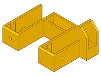
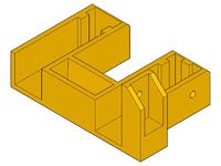
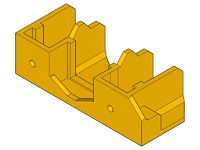
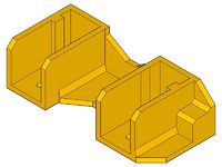
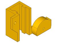
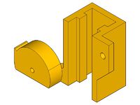
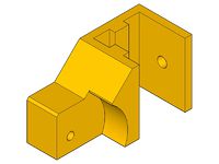
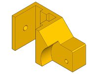
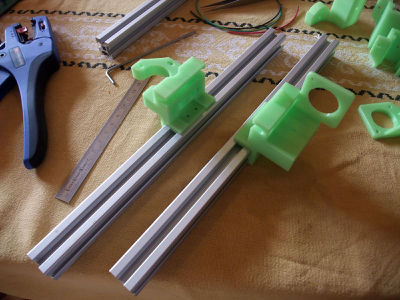
Know the parts
Firstly, have a look at all the part and learn what everything is.
foot-front left
foot-front right
foot-rear left
foot-rear right
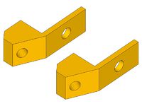
hinge-outer left
hinge-outer right
hinge-inner left
hinge-Inner right
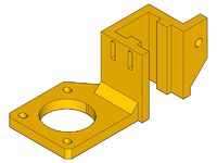
z-motor-bracket left
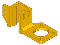
z-motor-bracket right
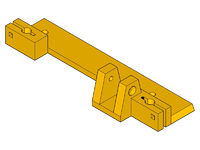
y-idler
y-motor
y-carriage
belt-clamp
x-end motor
x-end idler
z-top left
z-top right
x-carriage
extruder-idler
board mounts
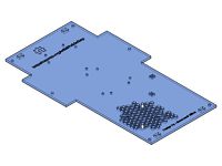
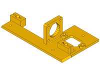
underplate
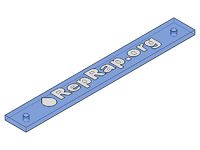
reprap.org plate

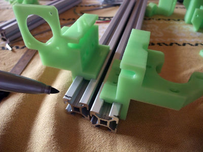
How to insert a T-nut
 Tightening torque : 2.5 Nm (+/- 5%)
<videoflash>9CAiVmfO2mk|320|240</videoflash>
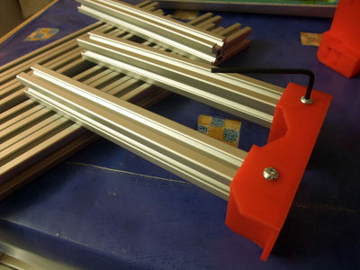
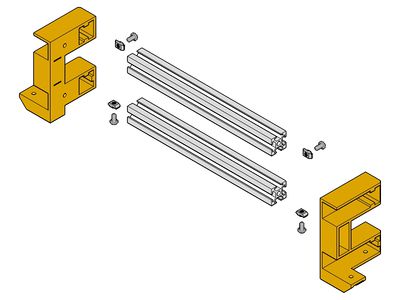
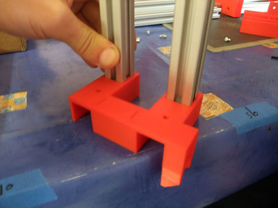
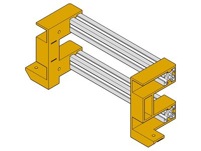
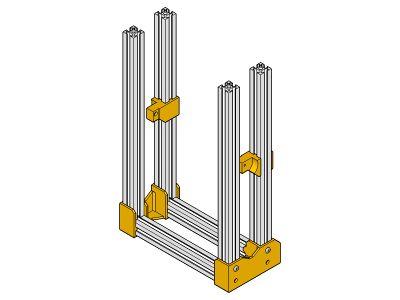
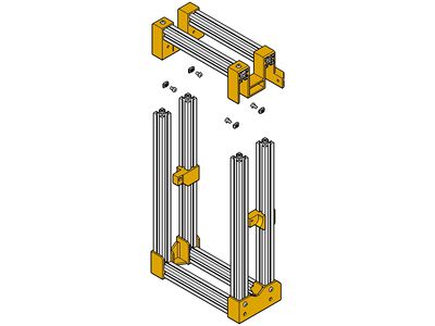
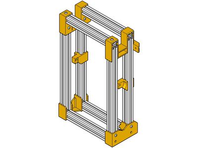
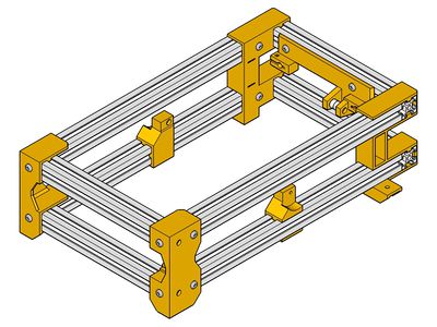
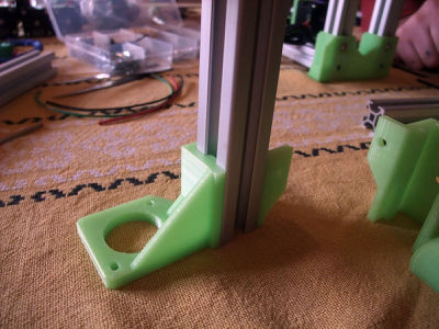
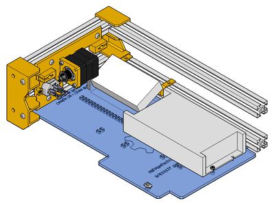
Base Frame
Rear Base
 x1
x1
 x1
x1
 x2
x2
 x4 m4x8
 x4 t-nut
exploded view
tips : use the other extrusions to help you while adding the first two nuts
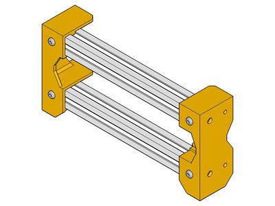
assembled


<videoflash>R-FKKoWC1hw|320|240</videoflash>
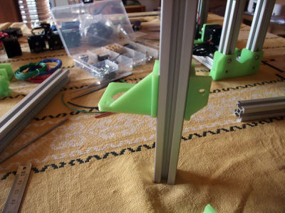
Front Base
 x1
x1
 x1
x2
x4 m4x8
x4 t-nut
x1
x2
x4 m4x8
x4 t-nut
exploded
tips: keep it flush by pushing the extrusion in from the flat side of the foot
assembled


<videoflash>zFjVM068mtI|320|240</videoflash>
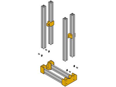
Base Frame
 x1
x1
 x1
x1
 x1
x1
 x1
x1
 x4
x10 m4x8
x10 t-nut
x4
x10 m4x8
x10 t-nut
slide the hinge-inners on two 300mm extrusions
it's not yet necessary to lock the hinges


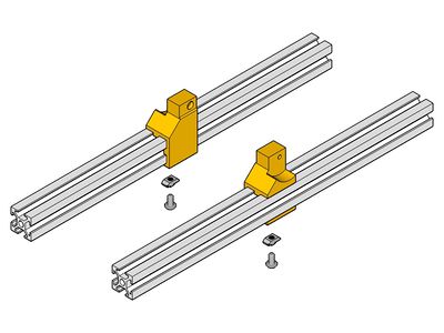
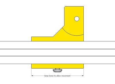
Y-idler

 x1 m3x20
 x2 (603zz)
 x2 m3 washer
x2 m4x8
x2 t-nut
x2 m3 washer
x2 m4x8
x2 t-nut
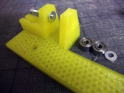
tips : it's easier to add everything while holding the y-idler in vertical position
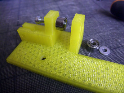
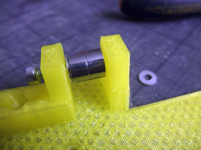
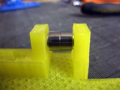
then add it on the frame, don't fully tighten the T-nut, you will need to move it slightly later to center it


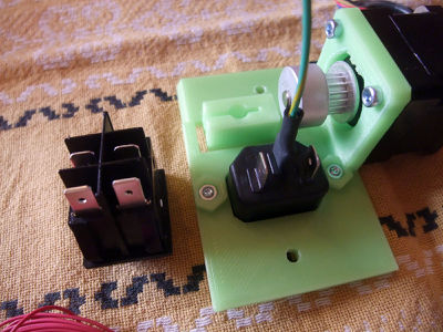
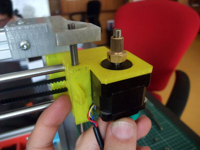
Y-motor
Plug
 x1 y-motor.stl
 x1 plug
 x2 m3 nut
 x2 m3x8
add the male plug with 2 m3x8 and 2 m3 nut


Motor
x2 m3x8
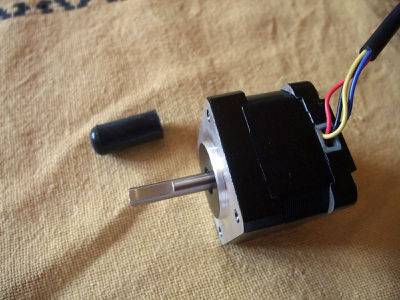
 x1 nema 14 stepper motor
 x1 pulley
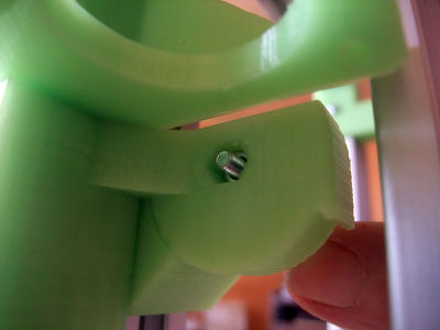
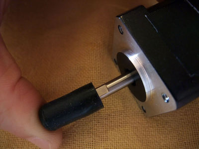
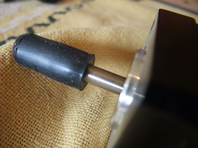
add the pulley on the motor shaft, and lock it with the grubscrew on the flat of the shaft
add the motor with 2 or 3 m3x8, the wires pointing downward
sometimes the pulley shape can vary, don't worry about it, as long as the flange is aligned along the plastic


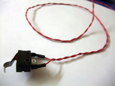
Plug-Switch Wiring
 x7 ferules
 heat-shrink sleeve
 x1 switch
x3 m4x8
x3 t-nut
x1 switch
x3 m4x8
x3 t-nut
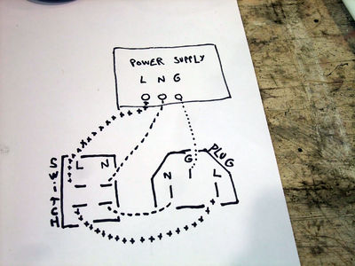
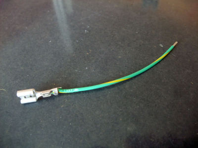
cut some wires : 1 green wire 18WG of 10cm, one end with ferule, the other end just stripped (male plug Ground to power supply Ground)
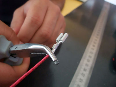
crimp the ferules on the wires
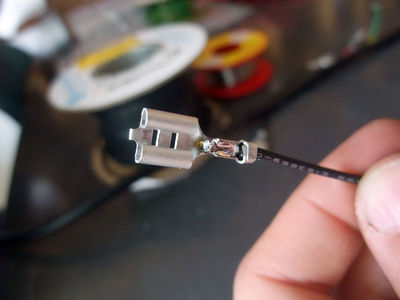
eventually add a drop of solder to make a perfect connection
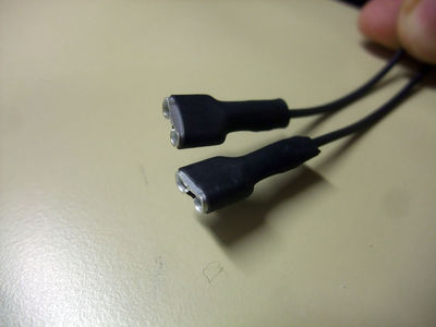
don't forget to insulate the ferules with the heatshrink sleeve
the green wire in place, now to the red/black ones !
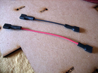
1 red wire of 9cm, 1 black of 6-7cm 18AWG, both ends with ferule (male plug Live/Neutral to switch Live/Neutral)
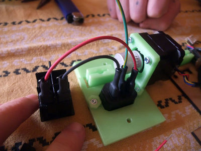
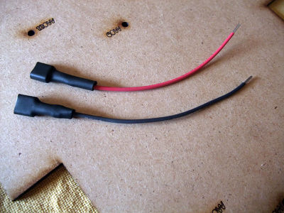
1 red and 1 black wire 18AWG of 10cm, one end with ferule, the other end just stripped (blue-switch Live/Neutral to power supply Live/Neutral). You may need longer wires depending of the power supply and it's position on the underplate, it may be good to shorten them later, once the psu is in place.
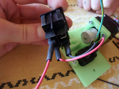
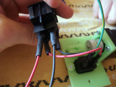
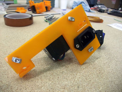
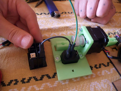
add the t-nuts
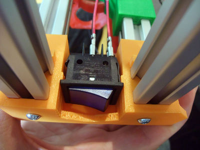
put the big blue switch in the rear-foot
now you can lock the Y-motor while pushing it against the same rear foot (the two small bumps helps to center the Y-motor)
pay attention to really lock the t-nut near the plug, as it is easy for now and later you will push against it when you plug the power cable in


A part of the wiring depend of the combination of electronic board and power supply, for other version : FoldaRap_power-supplies
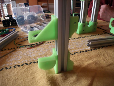
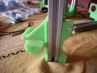
Z-axis
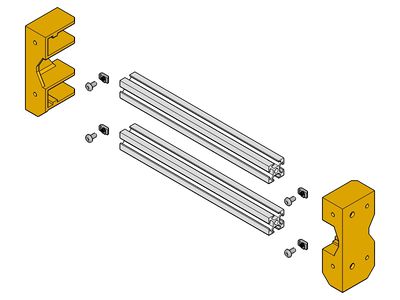
Caution : on the aluminium extrusion some corners are better than others, take care to choose one that slide well for the X-motor and X-idler, keep it in mind then when assembling the Z-right and Z-left.


Z-Left / Z-Right
 x1
x1
 x1
x1
 x1
x1
 x1
x1
x2
x4
x4
Do the same for the other side


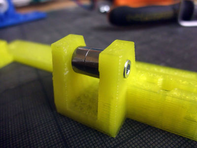
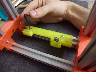
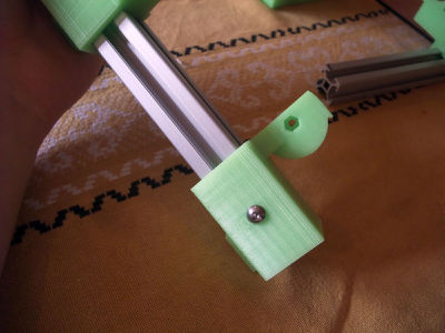
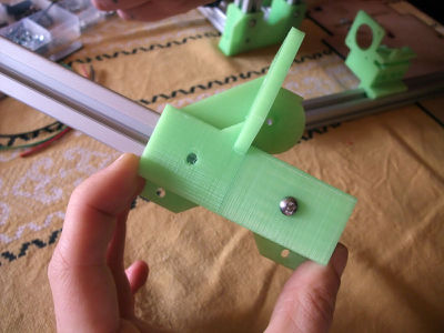
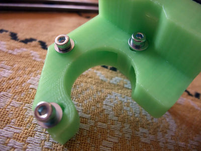
Hinges
Hinge principle :


x2
x2
Do the same for the other side :)


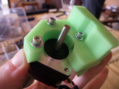
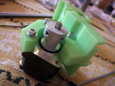
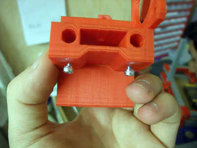
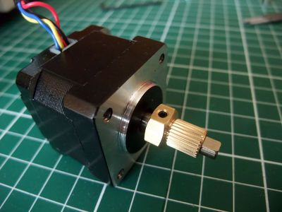
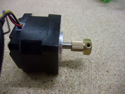
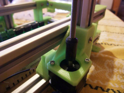
Z-Motors
x2
x4
- +vinyl coupling x2
pushed half-length on the motor shaft
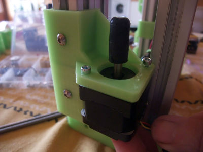
then add the motor with two m3x8 bolts
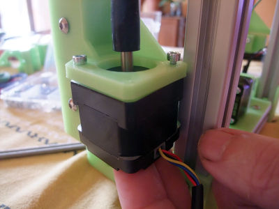
pay attention to the wires orientation


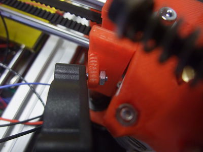
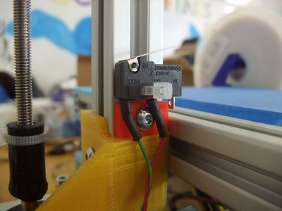
Z-endstop
 x1 (with 25cm blue wires for z-endstop, fix with an m3x8 or simply use a glue gun)
people usually twist the wires of the endstop and motors, to reduce interferences and make them more tidy
the lever is oriented toward the left (exterior)


Underplate
Power Supply
Different kind of power supply have been used in FoldaRap builds, if you don't recognize yours look at this page : FoldaRap power-supplies
Anyway, the principle is always 1) bolt the power supply on the plate, 2) then the plate on the base of the frame
 x1 power supply
x2 m3x8
x2 m3 nut
x1 power supply
x2 m3x8
x2 m3 nut
 x1 lasercut underplate
x6 m4x8
x6 t-nut
x1 lasercut underplate
x6 m4x8
x6 t-nut


Z-axis 2
x6
x6
- Now you can push the hinge against the plate and lock the two Z at right angle with the frame


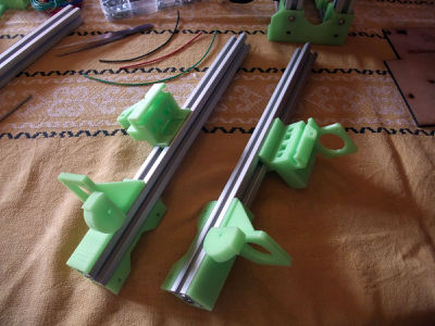
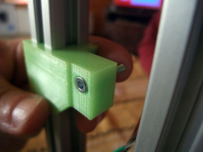
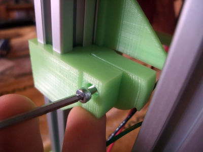
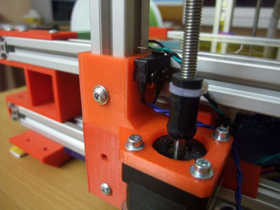
X-axis
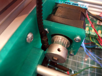
X-motor
The holes for mounting the motor are wide in order to be able to use them for adding tension on the X belt. Thus mount the motor as close as possible to the extrusion side in order to be able to push the motor the other way arround at the tensionning step.


 x1
x1
 x3
x3
x1 (50cm wires)
x1
x3
x3
x1 (50cm wires)
x1
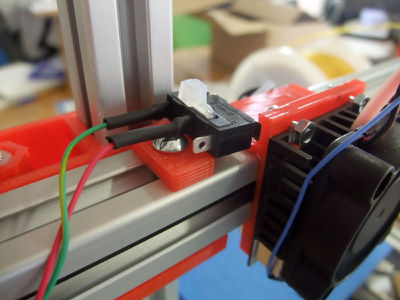
x1 (with 50cm red 26AWG wires for x-endstop, fix with an m3x8 or glue gun)
(the motor can be mounted on either side of the part but don't forget to adjust the firmware correspondingly!)
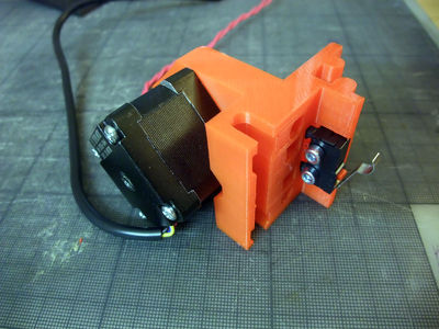
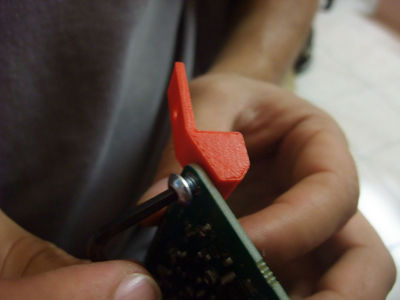
then glue the endstop


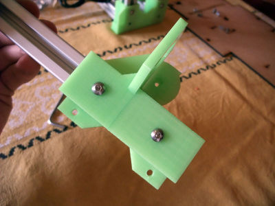
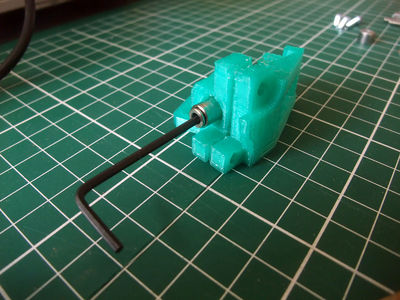
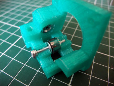
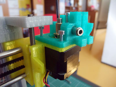
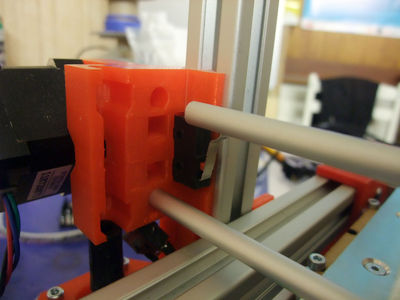
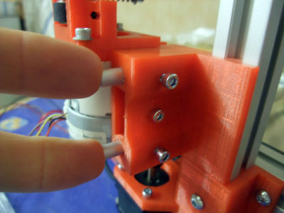
X-idler
 x1
x2 m3x8
x2
x1
x2 m3x8
x2
 x1 m3x12
x2
x1
x1 m3x12
x2
x1
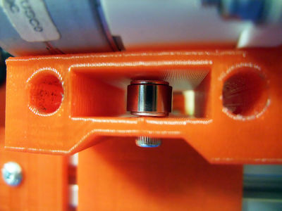
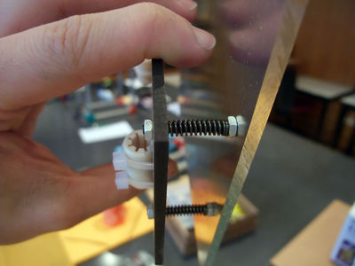
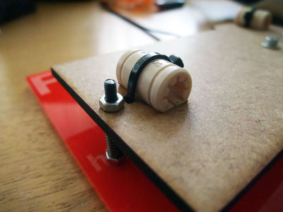
to add the idler bearing easily, start by pushing the bolt, add one washer, the bearing, turn it upside down and add the second washer by using it to push the bearing upward, to finish the bolt is screwed into the plastic and don't need a nut
after having checked that the smooth rods can slide without force in their holes, add an m3 nut in each, it will be trapped and will serve to hold two m3x8 bolt to lock the smooth-rods


After wiring, put the two x-ends in place (impregnate the printed parts with oil for better sliding) and add the smooth-rod without forgetting the three linear bearings.
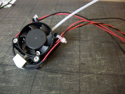
Extruder-fan
(Optional)
 x1
x1 m3x16
x1
x1
x1 m3x16
x1
If the bolt don't screw in the plastic, add a nut, but this one can be tricky to put in place.

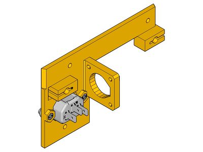
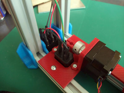
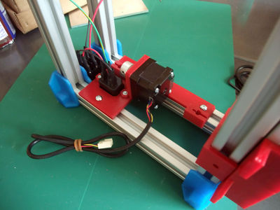
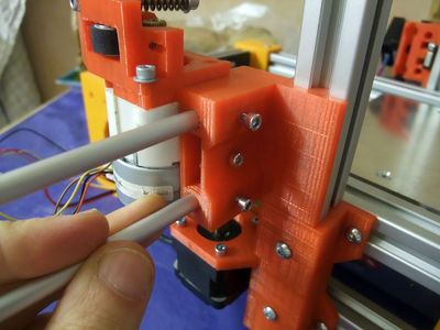
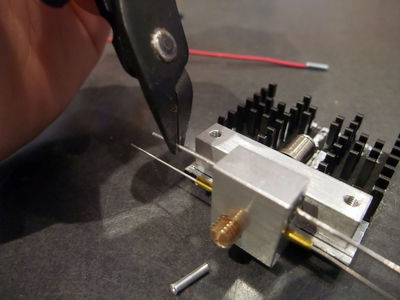
Extruder-idler
For previous version using a geared PG35L see FoldaRap_PG35L

 x1
x1
 x1
x1
x1
x1
x2
x1 Nema14 (50cm)
x3
 x1 (just one)
 x2
x2
 x2
x2
x2
x2
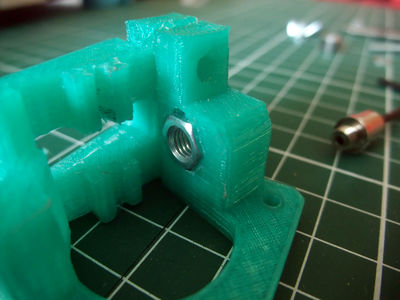
start by adding the M5 nut
if the entrance seems a little rough, you can make a small chamfer
add the pneumatic fitting
then the idler bearing
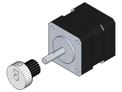
add the drive-gear on the motor shaft (make a flat if there isn't one)
(or like that, either way are possibles)
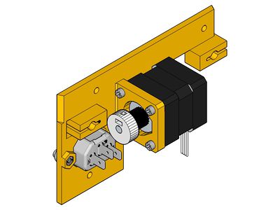
Then add the motor and the extruder-idler on the x-end-idler (which is sandwiched between both parts)
and finish by the springs


Top-frame
 x1
x1
 x1
x1
x1
x1
 x1
x1
x8
x8
<videoflash>xOSs5n_cQY4|320|240</videoflash>
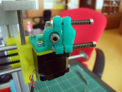
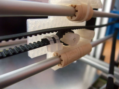
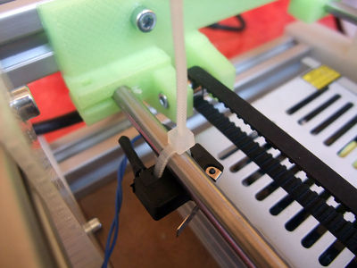
X-carriage
 x1
x1
 x2
x2
 x3 (LM6UU or igus RJMP-01-06)
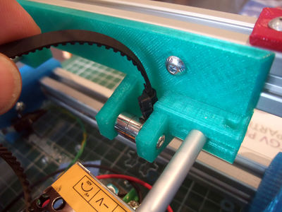
 x1 (700mm, longest of the two belts)
 x7
x7
<videoflash>mGf8y23Vfdc|320|240</videoflash>
don't forget to add the linear bearing/bushing on the smooth-rods


<videoflash>0r0LzsToHcs|320|240</videoflash>
- Now you can add some tension to the x-belt
<videoflash>sVjxMQwowbg|320|240</videoflash>
Z-rods
x4
 x2
x2
turn the rods in the x-ends to push them in the vinyl coupling

<videoflash>iZKFV5miQEk|320|240</videoflash>
Great ! You are almost done !

Have a pause, you need to be relaxed for the next step, or you can also just head to the end :)
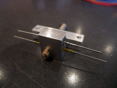
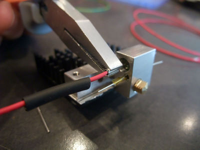
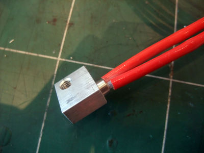
Hotend
x1 pneumatic-fitting
 x1 heatsink-block
 x1 nozzle
- cartridge heater
- thermistor 70cm 26awg
- fan prolongated to match 70cm
- see also the emaker huxley hotend
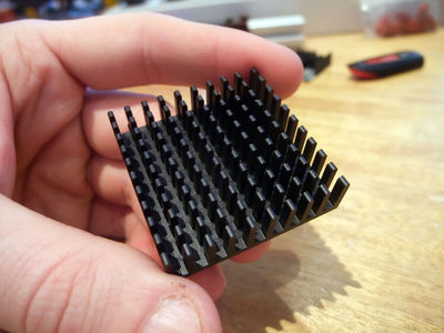
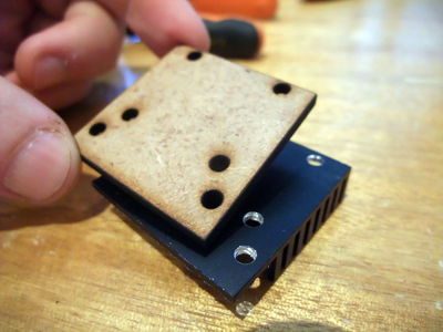
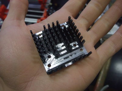
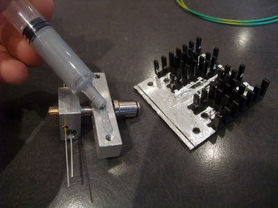
To prepare the heatsink you will need to remove some fins, drill a few holes and file a flat face (can be hand-made with a file, a dremel or machined)
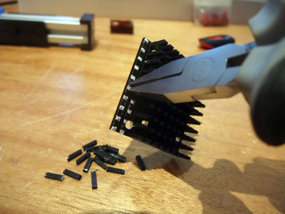
remove the fins by twisting them with a plier (found it easier and less dangerous than using a flush side cutter)
then use a template to drill the holes (for 3mm bolts)
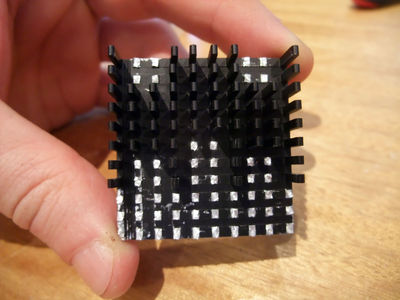
make the bottom of the heatsink flat (until no more black is apparent, like on the picture below) to make a good contact with the aluminium block that will be cooled
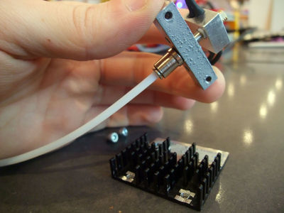
don't forget to put the ptfe tube in the pneumatic fitting, before adding the heatsink (the tube will fit snuggly between the fins)
add heatsink grease
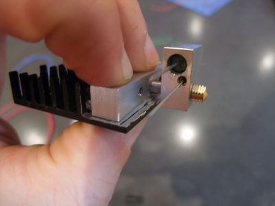
press firmly
engage both bolts
finish to tighten them (dont require much force as the taped hole is in the aluminium block)
the resistance have been replaced by a cartridge heater, but the logic is the same


- don't forget to tighten the hotend while being heated to 200°C (later, once you will have wired everying on the electronic board)
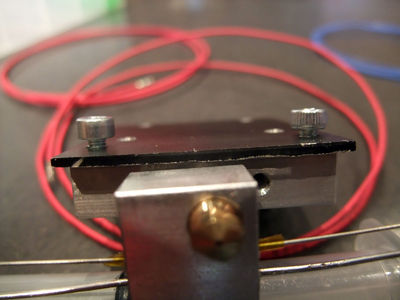
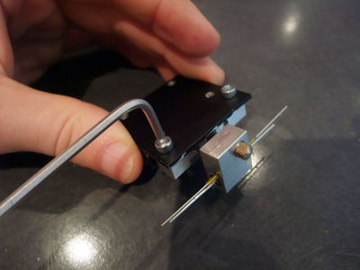
x3
x3
- You may need to add a nut to each bolt if spacing is needed between the heatsink and the linear bearings
<videoflash>yqNI2H22ZcY|320|240</videoflash>
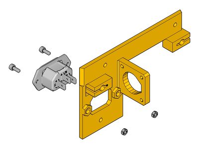
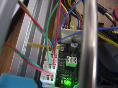
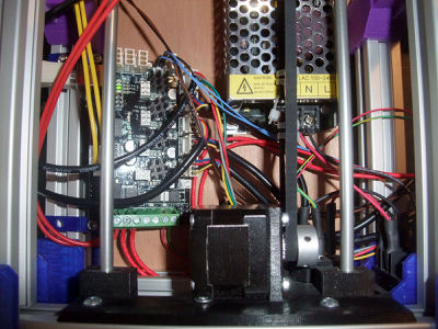
Electronic Board
Previous instructions for the AzteegX1 / Melzi
 x1
x1
 x1 board-mount
x2 m3x8
x2 m4x8
x2 t-nut
x1 board-mount
x2 m3x8
x2 m4x8
x2 t-nut
each board-mount is mounted to the board with a m3x8 and will use a t-nut to be held on the frame
you can put the board on the side you want but it is maybe better for the cable to put it near the y-motor (left of the picture)


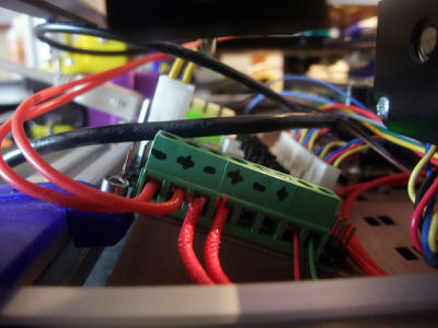
Wiring
Now lets plug everything to the board !

The Minitronics_10 page is well documented and the wiring should be quite easy with the molex connectors.
- It seems to use the same voltage reference as for a pololu (so we need to tune them to 0.4V, 0.45V)
Order/lenght :
Endstops
endstops use the S and - pins of the connectors
Y-endstop (green 25cm)
Z-endstop (blue 25cm)
X-endstop (red 50cm)


Motors
- Y-motor
- Z-motors
- X-motor
- Extruder-motor
Hotend(s)
- thermistor (blue 70cm)
- heater (red 70cm)
Fans

- hotend fan (red/black 60cm) : on the fan connector of the board or directly on the psu
- (optional) extruder-stepper fan: same
- (optional) printed-part cooling fan: on the "cooling fan" screw terminal (turned on by sending Mcode "M106 Sxxx" (xxx being between 0 and 255), turned off by "M107" but Slic3r automate this)
Bed
Finish by this one, as it is moving, the wires need to be above all the other wires.
- thermistor (blue 35cm)
- peltier
Voilà !
It may be a little messy at first but once finished everything is tidy and protected in the base of the machine :)


Tidying
- spiral wrapping band : for the wires that came out of the base (30cm left / 60cm right).
(image)
Y-axis
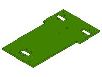
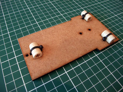
Bed-plate
If you have an aluminium heated bed look at this page : FoldaRap_Heated-Bed
 x1
x1
 x3
x3
x3
x3
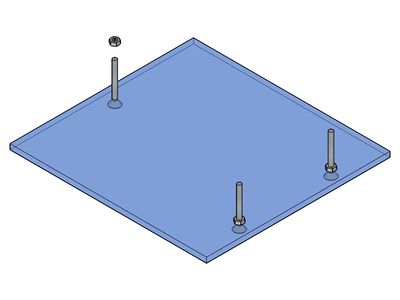
add the 3 countersunk m3x30 and lock them with m3 nut

Y-carriage
Other versions : FoldaRap1.0_y-carriage
 x1
x3
x4
x1
x3
x4
 x1
x1 (600mm)
x2
x2
x2
x1
x1 (600mm)
x2
x2
x2
 x3
x3
 x3
x3
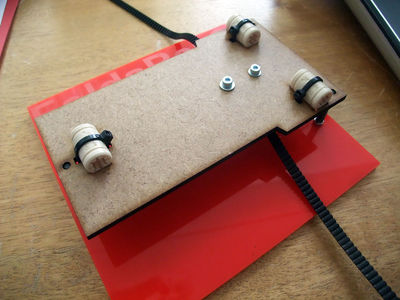
hold the linear bearing in place with zip-ties
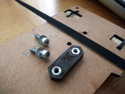
put the m3 nuts in the y-belt-clamp
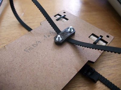
clamp the belt in the middle of it's length, try to clamp it on the middle of the belt-clamp too
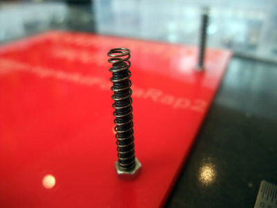
add springs on the bed's bolts
place the y-carriage
add the three m3 self locking nut (nylock)
tighten them a little (real leveling will be done just after)


Y-axis
x2
x1 (with 32cm green wires for y-endstop)
x6
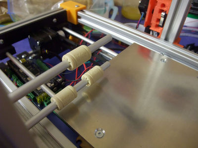
Slide the smooth rods through one side
then through the Y-carriage
and finish on the other side
The Y-motor was centered by the rear-foot-right, to align the Y-idler too check that the carriage run smoothly. By moving it will tend to center the Y-idler (or look that it seems at an equal distance from each front-foot. Once satisfied you can lock the Y-idler in place.
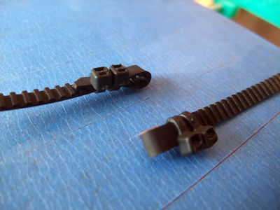
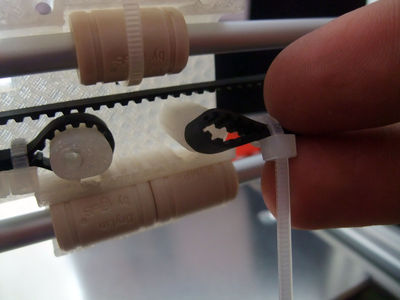
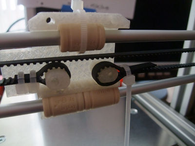
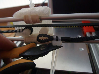
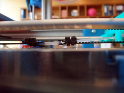
Make a loop at each end of the belt with zip-ties (pay attention to the orientation of the zip-ties)
pass it through the y-idler
and y-motor
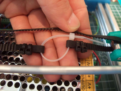
why the orientation is important
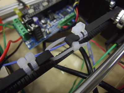
Tighten the belt by closing the loops with zip-ties, then trim everything (video of belt tensioning [1])
fix the Y-endstop on the smooth-rod with a zip-tie or glue it on the front-foot side


Tape (5-10 min)
Once the Y-axis is fitted it's easier to apply kapton (polyimide) or blue tape (outside masking tape, uv resistant and with acrylic adhesive)


<videoflash>MdCMMt7siy4|320|240</videoflash>
Leveling the bed and zeroing
The Z-zero is made when leveling the bed.
- Start by roughly leveling it
- then move the nozzle to the lowest point
- and adjust the 3 screws to level it regarding that height (by turning them until the homing move stop lowering the bed)
- repeat on each corners so the zero is exactly when the nozzle stop touching the bed (true for the four corners+center)
- I like to start with the X direction at the right bolt, then with the two at the left
<videoflash>35Xv_R8U_hU|320|240</videoflash>
Here is a video to show what I mean by "the homing move stop lowering the bed"
<videoflash>rjIMmzltyLQ|320|240</videoflash>
"Bad" (the bolts need to be tightened)
- Once the plan is set from left to right you can check front/end


- after that it's supposed to be leveled but may need few more tweaking for the right corners
Software side
- Skeinforge : you will only have to add a little offset (altitude), to have the desired height for the first layer, usually the same as your layer height.
- Slic3r : leave z-offset at 0, it will add one layer height automatically (you still may have to adjust it slightly to fine tune the Z-zero, depending on where your endstop have been glued).
Another advantage of that : by moving to the center of the bed from the zero height, the nozzle is also wiped by the side of the bed from any purged plastic ;-)
Go go go first print !!!

This article will probably help you along your first print :)
http://www.sarfata.org/3d-printing/2013/04/First-Steps-In-3D-Printing-With-Foldarap/
Also have a look at the User Manual