Wally
|
English • العربية • български • català • čeština • Deutsch • Ελληνικά • español • فارسی • français • hrvatski • magyar • italiano • română • 日本語 • 한국어 • lietuvių • Nederlands • norsk • polski • português • русский • Türkçe • українська • 中文(中国大陆) • 中文(台灣) • עברית • azərbaycanca • |
Release status: experimental

| Description | Linear bearing free 5 arm SCARA printer
|
| License | |
| Author | |
| Contributors | |
| Based-on | |
| Categories | |
| CAD Models | |
| External Link |
There is a lot more that needs to be added here but others have more knowledge of this printer, I have merely been an observer in the process. Check licence condition.
Wally is a modern SCARA design printer with a parallelogram constrained build bed elevation. It has no linear bearings and needs no timing belts. It uses a Bowden extruder and hot end and can work with the standard electronics with slicer or firmware changes for the kinematic calculations.
Developed to prototype stage by Nicholas Seward from brainstorming ideas by many on the "Delta robot 3D printers" Google Group in a thread titled "Delta mechanism variant" started by Billy Zelsnack and distilled further by user see3d when moving the development to RepRapForum, with continued brainstorming and prototype testing.
The completed printed part design by Nicholas is due for formal release on 22 September 2013 and he plans to sell a limited number of beta test kits for people to try out at cost before he contemplates crowd funding for production.
- Not to be confused with the Wallace RepRap.
Contents
Design Goals
- No linear rails
Specifications
- Build Volume:
- Build Area: 150 x 150mm or 200mm circle
- Build Height: mm
- Speed: mm/s
- Realistic Print Speed: mm/s
- Cost: $
- Estimated Build Time: hours
- largest part 175mm
Videos
Bill of Materials
Full BOM: https://github.com/NicholasSeward/ConceptFORGE/blob/master/Wally/wally.pdf?raw=true
1 HEAT PAD SILICONE
57 M3 NUT STEEL
46 M3x16 STEEL
27 608 BEARING STEEL
16 M8 NUT STEEL
15 M3x10 STEEL
13 M8 WASHER STEEL
10 M3x20 STEEL
6 M8x60 STEEL
4 M3x25 STEEL
4 M4x12 STEEL
4 M8x35 STEEL
4 M3x35 STEEL
3 M8x70 STEEL
2 M4 NUT STEEL
2 M8x85 STEEL
2 6702 BEARING STEEL
1 M8x100 STEEL
1 FILAMENT DRIVE BLOCK UHMW
4 NEMA17 STEPPER (40mm LONG) VARIES
3 STRING VARIES
1 POWER SUPPLY VARIES
1 CONTROLLER BOARD VARIES
1 HOT END VARIES
1 LEFT BOARD 1/2" FLATSTOCK
1 BOTTOM BOARD 1/2" FLATSTOCK
1 BACK BOARD 1/2" FLATSTOCK
1 BED BOARD 1/2" FLATSTOCK
1 RIGHT BOARD 1/2" FLATSTOCK
1 PRINT SURFACE BASALT
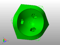
Printed Parts
Printing Wally is no small task. The printed parts take almost 1kg of PLA and 40-45 hours to print a complete set. Nicholas Seward recommends PLA printed at a 0.3mm layer height and 15% infill with 3 perimeters.
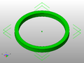
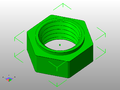
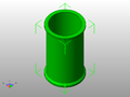
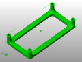
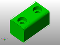
Below is a pictorial list of the printed parts required to build a Wally as of 11/12/13 from the ConceptFORGE github repository: https://github.com/NicholasSeward/ConceptFORGE. Beneath each photo is the quantity of each part to print based on the linked BOM from above.
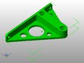
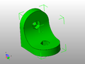
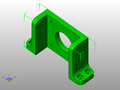
bed bracket right.stl, Qty: 1
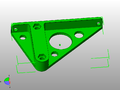
bed bracket right_MIR.stl, Qty: 1
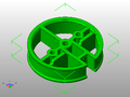
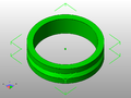
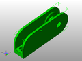
big pulley.stl, Qty: 2
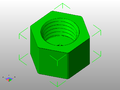
bowden nut.stl, Qty: 1
corner tab.stl, Qty: 2
edge tab.stl, Qty: 2
filament drive mount.stl, Qty: 1
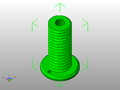
hub screw.stl, Qty: 1
hub washer.stl, Qty: 1
lock nut.stl, Qty: 1

plastic washer.stl, Qty: 4
spool holder.stl, Qty: 1
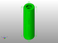
standoff.stl, Qty: 1
string tensioner.stl, Qty: 2
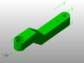
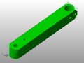
xy forearm.stl, Qty: 1
xy mount.stl, Qty: 2
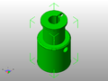
xy pulley.stl, Qty: 2
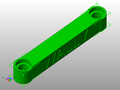
xy ubis mount arm.stl, Qty: 1
xy wall arm.stl, Qty: 6
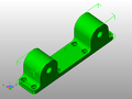
z arm wall bracket.stl, Qty: 2
z idler.stl, Qty: 1
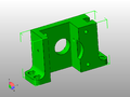
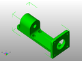
z motor mount.stl, Qty: 1
z pulley holder.stl, Qty: 1
z pulley.stl, Qty: 1


Firmware
Software
Assembly
Simple assembly with a little fiddling with the string drive.
One gotcha is that you will probably not be able to drop the 608 bearings into their holes. I put the part in an oven on low. I take it out every minute and hit it against a hard surface. When the tap turns to a thud you are ready to insert the bearings. I have heard reports that you can do this also by heating a bearing with a hot plate or heating the part with boiling water.
Homing
RepRapNess
- >% plastic
- <% hardware
- about % wooden bed and glass
- parts
- plastic parts
- unique parts
- unique printable parts
- hour replication time at 33mL/hour
- can print parts for larger than self version
Future Developments
- Exchangeable print heads
- Larger build volume
Brainstorming history
Distilled by user see3d.
Details about the concept
- Built off a rigid back board. The board can have ribs attached to make it more rigid. The material is TBD based on prototype needs.
- Wally could be designed to fold fairly flat for storage or portability. Think suitcase with a handle on the side. Legs could fold out to make it free standing, or it could be attached to a wall.
- The design can be scaled. Perhaps a 12" backboard width at the small end. That might give more than a 6" cube build volume. A 15" backboard width might give something on the order of 10" Diameter, or an 8" square, or a 10" x 7" Rectangle -- all with a 10" height. I think this would be a good design center.
- All axis are driven from stepper motors through a Spectra fishing line drive on preferably smooth pulleys.
- The two X,Y arms are driven by rotating the elbows. This gives a build area that is limited by an arc from the shoulder with a straight elbow to the hot end.
- The ratio of the stepper drive to large elbow pulley determines the resolution and torque. 0.025mm or better with a reasonable ratio with a 16-32x microstep.
- The Z axis is a 4 bar linkage that keeps the bed flat as it is rotated up and down through an arc. Gravity lowers and a stepper winding a string raises it.
- The build platform moves through an arc as the Z is changed. The X,Y Arms have to compensate for the displacement in the Y axis (perpendicular to the back board).
- A convenient place for a spool is on the lower back. Filament would be fed up through a Bowden extruder and over the top and down to the hot end.
Other brainstorming ideas
An end stop for both arms and possibly a table levelling Z probe might be able to be designed with just one microswitch located on the effector.
It might be possible to have a hot end tool changer. If the hot end is held with magnets on the effector, the hot end could be parked along the back wall to be picked up as needed. A strong hold magnet at the backboard could be magnetically adjusted to hold or release a tool. They would each have to have their own Bowden extruder. This would allow for multiple extrusion heads that stayed in the same centre of arm rotation, and did not require any reduction in build area.
With a universal holder design, things like a Laser Diode head, a light duty rotary cutter head, a magic marker, or a clay extruder could be accommodated. To offset some of the weight of a heavy tool, a counterbalancing string could be added from above. How practical these things would be would have to be tested in a prototype.
Links
- RepRap Development Forum: "Tri-Polar Bot Concept -- Meet Wally" for Wally design progress
- A reasonably current BOM and write-up
- James Hobson. Hackaday. "RepRap Wally Can Print Larger Versions of Itself".