RepRap Morgan
|
English • العربية • български • català • čeština • Deutsch • Ελληνικά • español • فارسی • français • hrvatski • magyar • italiano • română • 日本語 • 한국어 • lietuvių • Nederlands • norsk • polski • português • русский • Türkçe • українська • 中文(中国大陆) • 中文(台灣) • עברית • azərbaycanca • |
Release status: Working

| Description | RepRap Morgan Pro 2
|
| License | |
| Author | |
| Contributors | |
| Based-on | |
| Categories | RepRap Morgan / 5 lever armed robot SCARA
|
| CAD Models | OpenSCAD / LibreCAD
|
| External Link |
Reprap Morgan was designed to be an alternative to the norm, while conforming to the specification of the Gada Prize. In the opinion of the author the main problem prohibiting faster replication of RepRap system are:
- Cost of a stable structure, capable of a long service life at a high print quality
- Relatively hard to construct: Precise measurements are required
In addition to the GADA goals, the following goals will be added:
- Print, Snap and Tighten assembly process for the main system components (Done!)
- Vitamins should be kept to absolute minimum, and should be easily available, at very low cost - worldwide. (Done!)
- Vitamins should additionally be used keeping in mind their original design specification, in order to maximize vitamin lifetime. (Done!)
For the history and progress of RepRap Morgan, please see the author's reprap blog for a blow by blow account. http://www.morgan3dp.com (old blog: http://reprapmorgan.blogspot.com/ )
Contents
Buy one
Morgan has evolved into a commercial product. You can order your fully assembled Morgan Pro from Quentin Harley's Centurion Workshop. There is also a Morgan Mega (large 600x400x600 build plate) available on special order. Please enquire at http://www.reprapmorgan.com
Morgan in the Media
Quentin Harley's YouTube channel: http://www.youtube.com/user/quentinharley
Adam Oxford interviews Quentin Harley: http://www.youtube.com/watch?v=bZHpdRJKx7k
Hack a Day: http://hackaday.com/2013/02/08/scara-arm-3d-printer/ http://hackaday.com/2013/02/25/scara-arm-finally-prints-plastic-parts/
3dprintingindustry.com: http://3dprintingindustry.com/2013/06/03/reprap-morgan-in-its-natural-habitat/
Facebook Fanpage (quite new...): https://www.facebook.com/ReprapMorgan
Slashdot: RepRap Morgan Receives $20,000 Gada Prize For Simplifying 3D-Printer
Adam Oxford. htxt.africa . "South African wins $20 000 Gada prize for 3D printing".
Details
Morgan has evolved into a commercial product, with delayed publish open sourced plans. The latest Morgans run Smoothieware, on a custom made board "Speedyboard"
The months of October 2012 to March 2013 has been (so far) a period of renewed rapid development of the RepRap Morgan concept. There are some initial details on my blog: http://reprap.harleystudio.co.za
The complete unit mechanical design was done in OpenSCAD. Software / Firmware is based loosely off the Printrun / Marlin combination. Firmware is under development, but can be downloaded here: https://github.com/qharley/Marlin
Electronics used is RAMPS 1.4 for the prototype.
RepRap Morgan is based on the SCARA concept, and is unique because of it's motor placement, and concentric drive shafts. Planning and design started July 2011, and the project morphed through a couple of concepts and prototypes to get to this point:
The Scara concept as it is today started in December 2011, when I let go of an initial prototype because of the high vitamin count of that project.
The initial version of Morgan has been completed, and the STL and other source files are available, see below.
Video of exploded parts: http://www.youtube.com/watch?feature=player_embedded&v=vKEHL8pidwA
Files and Parts
Quentin Harley officially released the RepRap Morgan plans on May 14th, 2013. The STL files are located here https://github.com/qharley/Morgan/tree/master/stl
RobertKuhlmann's fork of the Morgan is at RepRap Morgan extended BOM (still under construction though)
DXF files can be used as basic templates to manufacture the platforms by hand. No laser-cutting required on a budget. The two prototypes were built using reused wood, hand-cut at no cost to the author.
A B.O.M. was created on kitbom.com: http://kitbom.com/WillAdams/reprap-morgan --- the specific parts need to be filled, esp. w/ purchase links, and all parts need to be verified as to accuracy of transcription and choice.
Queries about the afore-mentioned B.O.M.:
- 80mm is rather long for an M4 --- is there no other option?
60mm would also be acceptable (qharley)
- what torque rating should the 200 step stepper motor have?
0.5Nm is fine (qharley)
- PTFE tubing 6mm 600mm --- is the 6mm inside or outside diameter?
6mm OD (around 4mm ID)
- dimensions for the ``Universal Plate?
added to Morgan git
- dimensions for the Aluminum plate?
200x200mm
- specifics of the heat pad --- I picked 9 x 9 in. 200W --- OK?
PCB Heatbed Mk2a or similar (200x200mm)
- what gauge should the wire be? I picked 18ga
- Must the piping be brass? That's really going to blow the budget
    Copper plumbing is readily available, easy to work with and strong with a thin wall.
    Should not cost more than $4 to $6 for all of the copper piping. Brass was a mistake...
- What are the Cap_2 and TighteningCone_2?
Included in the Git repository. Used for clamping Bowden tube
Downloads
Bill of Materials as a .ods See also Reprap-Morgan-BOM-1.pdf
Full Morgan Hardware sources on Github: https://github.com/qharley/Morgan
Current Firmware: armlevel branch https://github.com/qharley/Marlin/tree/armlevel
Completed BOM with german translation: [1]
Assembly Instructions
(draft)
Copied from Initial assembly instructions
Note that this instruction is still a work in progress, and that it will change to incorporate images and improved instructions. A more usable assembly guide with exploded views is in the process of being created.
RepRAP Morgan is designed to be very easy to construct. Building it resembles playing with beads and a string, and only the order of the beads make it work...
Printing Morgan
If you did not get a kit, print the Morgan parts out of the material of your choice. I recommend using PLA for everything but the tool-head because of the rigidity of the material, and also because ABS tend to warp woefully on the larger Morgan parts. That said, if you can print the arms out of ABS without warp, it may be convenient to print the tool-head and the arm Psi-A in one piece...
Sourcing Vitamins
Most of the components will be available at your local hardware store. If in South-Africa, check out my SA 3D suppliers list for the harder to get stuff, like the Teflon tubing etc.
If Budget is of no concern, most exotics can be sourced though a company like RS components, but beware that with ease comes high cost!
More info in the Bill of Materials.
Pipe Assembly
Components:
- 2x PVC pipe 458.5mm long
- 2x PVC pipe 32mm 451.5mm long
- 4x Ported pipe adaptors
- 4x Non ported pipe adaptors
- 8x M4 nuts
- 8x M4 mounting bolts, countersunk heads 40mm
Insert the M4 nuts into the internal nut traps, and tighten / pull it in using the bolts. Do not remove the bolts at this time Mount the ported adaptors to the longer PVC pipes, using some PVC weld. Make absolutely sure that the ports face in oposite directions. The flat sides must be parallel. Mount the non-ported adaptors in the same way. Platform plans The plans for the platforms is a work in progress, but you can find it in the dxf folder of the git repository. I cut mine by hand, and a rotary tool, but it could be lasercut etc.
Install the bottom Z-mount piece on the lower platform. Install the top Z-mount piece to the bottom of the upper platform Drive Shaft Assembly
Components:
- 8mm Threaded rod - 650mm
- 15mm OD copper plumbing pipe - 440mm
- 22mm OD copper plumbing pipe - 460mm (to be verified)
- M8 Nut x 12
- M8 Bolt 40mm or similar (used as tool)
- M8 Nylock nut x 3
- M8 acorn nut (optional) x1
- M8 washer x 4
- M8 spring washer x 6
- M8 washer 28mm OD x 3
- 608Z bearing x 3 (of which 1 could be F608Z - recommended)
- Drive wheel Rod-mount (3D printed)
- Drive wheel Tube-mount (3D printed)
Take the 8mm threaded rod, and from one end, insert the following, rolling it towards the inside as you add the pieces:
M8 spring washer M8 nut M8 Spring washer M8 washer 608zz bearing, optionally F608Z flanged bearing, with the flange to the outside - recommended. M8 washer M8 spring washer M8 nut M8 washer, 28mm Rod mounted Drive wheel, with two captive M8 nuts - one on each end. M8 washer, 28mm M8 spring washer M8 Nut M8 Nut M8 washer 608zz M8 washer M8 Nylock nut Do not tighten anything yet, and let it sit loosely against each other on one end of the rod.
Prepare the 15mm copper pipe torsion support pipe:
Take a M8 bolt, and turn a M8 nylock nut onto it so that the lock part sits flush on the tip of the nut Support the pipe on a block of soft wood, and using a small hammer, gently knock the nut into the pipe until it is 80% in. Carefully pull the bolt and nut out of the pipe, and repeat on the other side. Supporting the pipe of the wood again, knock a standard M8 nut into each end until flush. Tap the edges of the pipe gently with the hammer to ensure a good hold onto the nut. Now from the other side of the threaded rod, turn the pipe with captive nuts onto the rod, and keep going until you almost reach the other components.
Insert the following after it:
M8 spring washer M8 nut With the bottom Nylock about 3 to 5mm from the end, tighten all the components against it, making sure to compress the spring washers until just flattened. Suspend the key components like the bearings and the nuts for the drive wheel nuts on PTFE plumbers tape, to ensure it gets fastened centred on the rod.
Push the 22mm pipe into the Tube-mount drive wheel, with the flat side of the wheel to the bottom. Ensure that there is just enough space at the bottom of the wheel for the 608 bearing. Install the wheel and pipe into the inner drive shaft by pushing it onto its 608 bearing.
Frame assembly
Install the pipes by carefully removing the bolts, and mounting it with the non-ported pipes to the back, and the ported pipes to the front. To Do: Image. Insert the smooth rods into the Z-holder Insert the drive assembly into the Z-holder Push the 6805 bearing adaptor onto the 22mm pipe, just a bit lower than the tops of the pipe. Insert the LMxUU bearings on the smooth rods, with or without the bed arms install the motors into the motor holders, and install on the base plate, making sure it clears the drive wheels. Install the top platfom on the pipes (careful not to lose the captive nuts inside), making sure the smooth rods gets inserted properly in the top z-mount holders. Mark the position of the 6805 bearing relative to the 22mm pipe. Remove the top platform (Did I mention the captive nuts), and push the 6805 adaptor to the correct position and install the 6805 bearing on it. This should lock the adaptor onto the pipe. Reinstall the top platform (Again, the nuts) and check for smooth movement of the 22mm tube on the bearings. Install the Arms on the driveshaft. (see Arm assembly and installation) Install the Drive Belts on the motors. Use the hole opposite to the arm orientation for both wheels respectively. Install the extruder on its mounting spot, and insert the Bowden adaptors if applicable Install the Z-drive motor onto the top platform Cut the lead screw to size, approximately 330mm long. If using the SDS lead screw, cut the SDS adaptor off right at the neck, and cut the tip of at the required length. Install the Z lead screw motor coupler piece onto the lead screw, using two M3 bolts and nuts. Insert the M3 captive nuts into the coupler, and install the M3 grub screws. insert one lead screw nut, and the 8mm spring onto the lead screw and insert it into the Z-mount bracket, followed by the second lead screw nut. Compress the spring to lock the second lead screw nut onto the screw. Install the bed arms (if not done before) by sliding the linear bearings into it from top and bottom. Insert the lead screw and bracket, and slide the bracket onto the bead arms from the bottom. Attach to the motor shaft using the three grub screws in the motor coupler. Arm assembly and installation
Prepare the arms:
Drill out the bearing cavities and tube areas using a 22mm step drill or similar, to achieve a smooth ID of exactly 22mm. Press fit M8 nuts into both ends of the Hex shafts of the Psi A and Psi B arms, as well as one M8 nut in the hex connector of the Theta B arm Insert two 608 bearings on the the bearing shaft of the Psi A arm. Prepare the 100mm and 40mm M8 bolts by turning PTFE plumbing tape onto the areas that will touch the bearings, and the captive nuts - for centering After the top platform is installed, fit the arm components onto the drive shaft in the following order:
Theta arm-A, with shaft pointing down 608z or F608z (recommended) M8 nut - Tighten down until the bearing touch the 22mm Pipe M8 spring washer M8 washer, 28mm Arm Psi-A, with the captive M8 nuts in the ends M8 Nylock (optional) M8 Acorn nut Again ensure that the components like the Arms and bearings sits on the rod, suspended on PTFE plumbing tape. This ensures that the components are completely centred on the rod, and will eliminate most of the potential shaft wobble.
When the final locknut has been tightened check for smooth movement of the two arms and the respective drive wheels.
Mark and cut the rod, leaving about 5mm from the nut, and install the acorn nut over it. Be sure to protect the machine from the metal filings by using some plastic bags or similar protection.
If the tool head is not integrated into the Psi-B arm, attach the tool-head to the arm Psi-B using two 2mm self-tapping coach screws, 40mm long. Attach Arm Psi-B to Psi A using the 100mm M8 bolt, pushed though the bearings in Psi A, followed by M8 nut, spring nut, and then the captive nuts of Psi-B. Secure with M8 washer 28mm, and M8 Nylock nut.
Insert the 6805 bearing into arm Theta B, and press fit over the Tool-head. If it does not have a tight fit, use PTFE tape on the toolhead to ensure a snug fit. Proceed to fit Theta B to Theta A using the 40mm M8 Bolt through the 608 bearing, followed by M8 spring washer, M8 washer, and the captive nut of Theta B. Secure with M8 washer 28mm and M8 Nylock nut.
Photos and Drawings
Exploded diagram: http://reprap.harleystudio.co.za/wp-content/uploads/2013/04/MLC-6.pdf
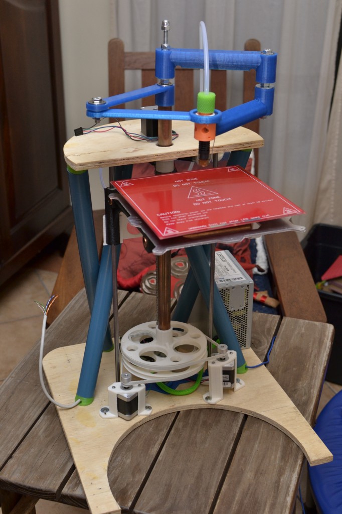
May 2013 shot of the Morgan Frame
RobertKuhlmann's forked Morgan project can be found here: User:RobertKuhlmann/RepRap Morgan
University of Wisconsin-Milwaukee undergraduate Morgan build project photos
Morgan Family
| Picture | Date of creation | Capacity (mm) (X,Y,Z) | Description | |
|---|---|---|---|---|
| Morgan v1 | 
|
~01/2013 | 200/200/~200 | The first Morgan by Quentin Harley |
| Morgan Pro | 
|
~06/2014 | 200/200/~200 | The second model |
| Morgan Mega | 
|
~03/2015 | 720/450/600 | The bigger comercial morgan model |
| Morgan Pro 2 |
|
~12/2015 | 380/220/200 | The last version of morgan Pro |
Further reading
- Buildlog from an early adopter
- General Delta and SCARA bot forum threads
- Development Forum for new generation Morgan ideas
- Just a few crazy Morgan ideas