Sanguinololu
|
English • العربية • български • català • čeština • Deutsch • Ελληνικά • español • فارسی • français • hrvatski • magyar • italiano • română • 日本語 • 한국어 • lietuvių • Nederlands • norsk • polski • português • русский • Türkçe • українська • 中文(中国大陆) • 中文(台灣) • עברית • azərbaycanca • |
- This page describes the Sanguinololu versions 0.7 and newer, including the current versions. For older versions see Sanguinololu_0.6.
Release status: working

| Description | Release Version 1.3a
|
| License | unknown
|
| Author | |
| Contributors | |
| Based-on | |
| Categories | |
| CAD Models | Eagle
|
| External Link |
Sanguinololu is a low-cost all-in-one electronics solution for Reprap and other CNC devices. It features an onboard Sanguino clone using the ATmega644P though a 644, 1284 or 1284P is easily dropped in. Its four axes are powered by Pololu pin compatible stepper drivers. The board is designed to be flexible in its power source, working with a 12V/5V ATX power supply or any 7V-35V power source via the on-board voltage regulator.
Contents
Features
- Small design – board is 100mm x 50mm (4" x 2") – barely an inch longer than a business card
- Sanguino clone, Atmel ATmega644P – ATmega1284 drop-in compatible
- 4 Pololu (compatible) stepper driver boards on-board (X,Y,Z,Extruder)
- Supports multiple power configurations
- – Logic and motors supplied by ATX power supply
- – Motors supplied by 5mm screw terminal 7-35V
- – Logic supplied by USB
- – Logic supplied by on-board voltage regulator
- Supports multiple communication configurations
- – FT232RL on-board for USB connectivity
- – USB2TTL header is available for FTDI cable or BlueSMIRF bluetooth module
- 2 thermistor connectors with circuitry
- 2 N-MOSFETs for extruder/heated bed
- Selectable 12v(or supply voltage)/5v endstop voltage
- Edge connectors enabling right-angle connections
- Silkscreen for connectors on both sides of the board, facilitating bottom cable connections
- 13 extra pins – 5 analog and 8 digital – available for expansion and development, with the following capabilities
- – UART1 (RX and TX)
- – I2C (SDA and SCL)
- – SPI (MOSI, MISO, SCK)
- – PWM (1)
- – Analog I/O (5)
- All through-hole components (except FTDI chip) for easy DIY soldering
Derivatives
The Sanguinololu design has spawned several derivatives, including the Teensylu, which replaces the microcontroller with one supporting on-board USB, rendering the FT232RL superfluous, and following on from that the Printrboard, which also has directly incorporated stepper drivers and SD card reader on-board.
Bugs
- The USB 5V VBUS is connected to the output of the 5V regulator. This is bad for the regulator and bad for the PC. Some users report the regulator getting very hot (because it is trying to power the PC), other users report the PC giving USB over current errors. Nophead and Nothinman recommend cutting the 5V track to the USB connector. The only downside is the board needs the 12V supply before it will do anything, but who cares?
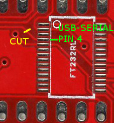
- An alternate fix for the 1.3a board is to cut the trace between the USB chip pin 4 and C13. This is functionally identical to building a Sanguinololu without the USB port and FT232RL and using an offboard USB-serial cable. The advantage over cutting the 5V trace at the USB connector is that the USB serial port doesn't disappear from the host PC when the printer is switched off, which can anger host software that is still running.
- Another fix that seems to work using Schottky diodes: http://forums.reprap.org/read.php?158,400825
- Another fix is to strip the insulation and shield from the USB cable and cut the 5V wire. This has the advantages that, if the board is powered off, another cable with all wires intact can be used to communicate with the board and it does not require a board modification. The 5V wire can be identified by searching for USB pinouts and can be checked by sticking a needle through the wire insulation to measure conductivity.
- When the bootstrap loader runs during reset and when downloading firmware the motors are enabled due to pull-downs on the Pololus (The enable pins are pulled up by 100K resistors on the Sanguinololu but they are pulled down by 100K on each Pololu). The step pins are floating and this can cause random motor movements. The E step pin is next to E dir pin which the bootstrap thinks is an LED to be flashed. Crosstalk can cause the extruder to spin when firmware is being loaded. This is not good as it will be cold, so could damage the hot end. Nophead recommends changing the enable line pull ups (R7 and R8) to 4K7 to ensure the motors are disabled until the firmware enables them.
- A software fix is to use the the Gen7 boot strap that does not flash the non-existent LED.
- The pads and traces on the board are not robust enough to handle the high current involved when controlling the heated bed with the sanguinololu's dedicated mosfet. If left as is, the board will heat up in this area, could be damaged and the plastic connectors discolored. To fix, simply add a direct current path by way of (preferably insulated) wire from the 12v input to the 12v pins on the Heated Bed (HB) connector; from the center pin of the HB mosfet to the two ground pins on the HB connector; and from the ground pin on the mosfet to the ground input of the board (probably the ground side of the 12v connector). Find the appropriate traces using continuity check or resistance mode on your multimeter, and check after to ensure you didn't create a short between any of these components in the process. It would be prudent to check for shorts before starting so you don't waste effort trying to fix a short you think you just created but was already there before you applied this fix. To understand this fix, pretend that no traces exist between the high current pathways of the 12v input and 12v pins of the HB connector; the ground input and the ground pin on the mosfet, and the center pin of the mosfet and ground pins on the HB connector. Assume you must create these pathways, then do so!
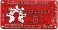
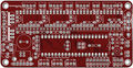
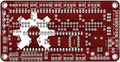
Schematic & Board Images
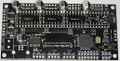
1.3b2 Top
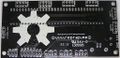
1.3b2 Bottom
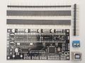
1.3b2 With thru-hole components unassebled


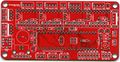
1.3a Top
1.3a Bottom
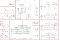
1.3a sch


Reference Renders
(Click to view older versions.)
Board top
Board bottom
Board schematic


Where to get it
You can get the bare pcb, a complete kit or assembled boards at:
- Blomker Industries (1.3a assembled, 644P)
- RepRap.me (1.3b2 kit, 1284P)
- SainSmart (1.3a assembled, 1284P)
- XYZ Printers (1.3a bare pcb, kit, 644P)
(If any other resellers have this available, please add to this section.)
You will also need four Pololu stepper drivers or compatibles like the StepStick.
EAGLE files, parts list
Schematics, board layout, images: https://github.com/mosfet/Sanguinololu/tree/master/rev1.3a
Parts list: https://github.com/mosfet/Sanguinololu/blob/master/rev1.3a/parts.txt
| |
Caution This parts list is reported to be both incorrect and incomplete. The IC should be a 644P, not simply a 644. Check the assembly instructions (below) for the parts needed. Also, ensure to buy 1/4 watt resistors, since larger ones won't fit the PCB. |
Assembly Instructions
For users soldering a 1.3a board:
- You'll have a 2-pin male header and jumper shunt to solder for the AUTO-RST function of the FTDI. This is located right above the ATmega chip. TODO: Get pics and incorporate this into the instructions below.
A step-by-step build guide to the 1.2 PCB is available with low, medium and high resolution images.
Modifying Older Boards (from Version 1.1 and 1.2 to Version 1.3a)
To modify a v1.1 PCB to make it (electrically/firmware) equivalent to a v1.2 PCB, the image below and this drawing show the track cuts and additional wire links required.

| |
Note Wire bridges are now used in place of R7 and R8 on v1.2 and v1.1 boards modified to v1.2 electrical/firmware equivalence. |
To create a 1.3a equivalent PCB from a v1.1 board modified as above, or a standard v1.2 board, the following changes are required:
- Mount C7 in a socket so that it can be unplugged - as per Adrians Prusa Notes.
- Adding two 100k pull-up resisitors, one each between 5V and Pin 20 and Pin 35 of the ATmega chip.
| |
Caution As at 2011-09-12 the above mod (from v1.1 modded or v1.2 standard to v1.3a) has yet to be functionally tested/verified. |
Introduction
Gather the tools you will need to perform through-hole soldering, and if you opted for the on-board FTDI IC, some SMT soldering as well. Soldering pencil and/or iron, solder, and most importantly: flux! I can't stress how much easier flux makes soldering the SMT device.
Carefully inspect your board for defects. Look for strange connections between traces. Become familiar with the locations of devices from the back as well as the front.
Gather your components and ensure you have the complete parts list for your selection. This photo shows enough parts for two Sanguinololus - one with ATX connectors and the other with screw terminal and voltage regulator.

Soldering the FTDI USB to serial IC
Install the FT232RL FTDI IC. Note the orientation of the silkscreen. Solder using your favourite SMT soldering method. The board pictured was tinned from the fabrication shop. After applying flux to the pads, and carefully placing the chip, it was easily soldered by touching the tip of the soldering pencil to the end of a pad to tack the chip down, and then on the pin itself to flow the solder correctly. If you're not sure you want to tackle the SMT soldering, boards are available with this IC pre-soldered. An alternative is to use a USB to TTL-converter instead of this IC.
Parts:
IC100 FT232RL FT232RLSSOP


Next install the FT232RL support components, minding the polarization of the electrolytic capacitor (C16).
Parts:
 J1       USB              USBPTH
 C7       0.1uF            CAPPTH2
 C8       0.1uF            CAPPTH2
 C11      0.1uF            CAPPTH2
 C15      0.1uF            CAPPTH2
 C16      4.7uF            CAP_POLPTH2

Now is a good time to test the FTDI chip. Plug a USB cable into the port. The device should show up as a COM port or a TTY device and allow itself to be opened. If you temporarily connect the 'TX' and 'RX' pins on the USB2TTL port on the back of the board anything you type in your terminal application (such as PuTTy) should be echoed back to you. Be sure that your jumper doesn't short to the case of the USB connector just below it and fool you into thinking you have a problem when you do not.
Note that when you have finished the assembly and want to connect to the board using your printer software, then if you are using Windows XP you will need to load the FTDI drivers from the FTDI Virtual Com Port Drivers webpage. As of (2015?) FTDI made driver installation noticeably easier on a machine running Windows. Only one Windows setup executable file should be required to be downloaded and installed, though it is still possible to do it manually by downloading the CPU dependent (32 or 64-bit) CDM zip archive from the same webpage. After the drivers are installed by either method, on first connecting Sanguinolou via USB cable to a computer running Windows, the FTDI chip will be recognized and the the driver install process will be completed.
Soldering the Sanguinololu core
Next, solder the female headers, making sure they're straight and completely seated on the PCB. Where two lengths of header strip are placed so they join in the middle, they may be fractionally too long to lie flat on the board at the join. In this case, carefully file off some of the plastic at the adjoining ends until they fit together in the space available.
Parts:
4x Female Pin Header 16 Pin

Solder MS1, MS2 and MS3 jumper headers. I find that it is easier to solder the 2-pin header if the jumper shunt is installed. Ensure they're completely seated and straight. Leaving the jumper shunt in place will pull the MS pins high, i.e. set the Pololu controller to sixteenth step resolution. This turned out to be the appropriate setting for my out-of-the-box firmware. If your motors move erratically, check these.
Parts:
 12x Male Pin Header 2 Pin
 12x Jumper Shunt

Install the LED current-limiting resistor and the MS1 pull-down resistors (MS2 and MS3 have internal pull-down resistors).
Parts:
 R1       1k (1.5k)        RESISTORPTH1
 R2       100k             RESISTORPTH1
 R3       100k             RESISTORPTH1
 R4       100k             RESISTORPTH1
 R5       100k             RESISTORPTH1

Solder the driver decoupling capacitors. Before soldering, bend the leads to the side so the capacitor lays down. Mind the polarization!
Parts:
 C1       100uf            CAP_POLPTH1
 C2       100uf            CAP_POLPTH1
 C3       100uf            CAP_POLPTH1
 C4       100uf            CAP_POLPTH1

Install the thermistor high pass RC filters. Mind the polarization of the capacitors. Install the MOSFET pulldown resistors.
| |
Important Note If you're building a Sanguinololu 1.3a, install 100K resistors as R7 and R8. If you're building a Sanguinololu 1.2, do not install resistors in R7 and R8. Instead, replace them with wire jumpers - for example, two clipped leads from a previously soldered part. |
Parts:
 R6       10k               RESISTORPTH1
 R11      10k               RESISTORPTH1
 R7       100k - 1.3a only! RESISTORPTH1
 R8       100k - 1.3a only! RESISTORPTH1
 C9       10uF              CAP_POLPTH2
 C10      10uF              CAP_POLPTH2
 R9       4.7k              RESISTORPTH1
 R10      4.7k              RESISTORPTH1

Install the DIP socket and ceramic resonator. Before soldering, bend the resonator leads so that it lays down within the dip socket. It doesn't matter which way round it goes.
Parts:
 DIP-40   SOCKET
 Y1       16MHz 22pF       RESONATORPTH

Install the two ceramic caps for the ATmega and the reset pull up resistor.
Parts:
 C14      0.1uF            CAPPTH2
 C13      0.1uF            CAPPTH2
 R12      100k             RESISTORPTH1

Solder the MOSFETs, the large charge capacitor, the reset button, and the power LED. The power LED's negative lead is on the flat side, or the shorter lead. The negative lead goes to the left in the picture.
Parts:
 Q1       RFP30N06LE       MOSFET-NCHANNELPTH2
 Q2       RFP30N06LE       MOSFET-NCHANNELPTH2
 C12      1000uF           CAP_POLPTH4
 S1       RESET            TAC_SWITCHPTH
 LED1     POWER            LED3MM

ATX power supply
If you are using the ATX power supply, install those connectors.
Parts:
 ATX1     ATX-4VERTICAL    ATX-4VERTICAL
 HDDPWR   5v/12v           DRIVEPWRVERTICAL

| |
Important Note It has been suggested (thanks Kliment & tonokip) that the 5V coming from the ATX power supply may not be as stable at 5V as one could hope. It would be better here instead of using the 4-pin hard-drive connector to use only the 4-pin ATX connector and the voltage regulator. The 4-pin ATX connector will still provide enough power for the board. One could even forgo the voltage regulator and power the logic side of the board solely by USB. |
Voltage regulator & screw terminal
If you are using the voltage regulator and screw terminal, install those parts now. Note the orientation of the LM7805. Label the screw terminal with a felt tip marker which side is positive and which is negative. On later versions of the board the screw terminals mount at right angles to the way shown so the wire they connect to comes out parallel to the USB lead.
Parts:
 IC1      LM7805           VREG
 C5       0.33uF           CAPPTH2
 C6       0.1uF            CAPPTH2
 JP23     SCREW            M025MM

Connectors
Finally, solder the motor, end stop, thermistor, and bed/tip connectors. Optionally solder the 12V (or supply voltage) connectors along the top of the board, and the ISP 6-pin header (for programming the ATmega).

For speeding up the soldering of the connectors in case you use pin headers, you can use longer strips and just snip the unused positions, like this (top strip left, endstops right), resulting in a board as shown:


Alternative build, using IRLB8743 Mosfet
See [Create3D.com.au],
Step 1
Solder FTDI chip on back of PCB,
4 X 0.1uF (100nF) capacitors to C7, C8, C11, C15
1 X 10uF capacitor goes in C16, change from Sanguinolu, square marking notes positive anode
1 X USB hub
attach USB to computer and confirm the FTDI chip is read
Step 2
R1 1k or 1.5k
R2 100k
R3 100k
R4 100k
R5 100k
R6 4.7k (create3D)
R11 4.7k (create3D)
R7 100k
R8 100k
R9 4.7k
R10 4.7k
Capacitors, note polarity
C1 100uF, bent flat
C2 100uF, bent flat
C3 100uF, bent flat
C4 100uF, bent flat
C9 10uF
C10 10uF
C6 100nF, optional, if LM7805 is used
Step 3
2 Pin Jumper Shunt X12
32 Pin Header X2
Step 4
Y1 16Mhz 22pF Ceramic Resonator, bend it flat, label up
C13 100nF
C14 100nF
R12 100k
Dip 40 Socket, note alignment to co-ordinate with chip
optional 2X1 header
Step 5
Q1 MOSFET
Q2 MOSFET
C12 1000uF
S1 Tact Switch
LED1 Green, 3mm, the - lead goes left, the + lead is nearest the corner hole
INCOMPLETE
Missing IC1 LM7805
Missing C5 0.33uF, right of LM7805
Missing power
Missing headers
These all go depending on power and pin layout decision.
EXTERNAL
Pololus
When you solder the pin strips onto the Pololus you will find it easiest to insert the strips in the appropriate place in the Sanguinololu. Then just drop the Pololu boards on top and solder them in place. Check the polarity is correct - don't trust checking it against an image on this wiki. Make sure that pins 1a, 1b, 2a, & 2b are closest to the edge of the board. You can then unplug them later if you want.
Endstops
Mechanical micro-switch endstops are recommended for their simplicity and reliability. It is recommended to wire the switch terminals Common (C) and Normally Open (NO) to GND and SIG on Sanguinololu (the two outside pins on the endstop connectors). Ensure you set Endstops_Inverting to true in your firmware.
If you are using optical endstops or proximity sensors (or other endstops that require power) you can use either 5V or 12V (or supply voltage) depending on what endstop device you want to use. This is selected by soldering a little link labeled "Stop Volt" on the back of the board. With the text the right way up, joining the left pad to the middle one gives 12V (or supply voltage), right to middle gives 5V. Take care not to short all three together.
Fan
The 1.3a board does not have a separate PWM output for a 12 V cooling fan. You can adapt a spare 5 V output with a firmware edit and an external power transistor circuit. Example here.
Software
| |
Caution The detailed instructions in this section are outdated. They apply to the ATmega644P and old Arduino IDEs only. For more recent instructions, refer to the Arduino IDE Support page for the Gen7 electronics. This includes downloads, installation instructions and bootloader upload instructions. It will show you how to handle the ATmega644, ATmega644P and ATmega1284P and how to make use of recent Arduino IDEs. The Gen7 Arduino IDE support package works for a Sanguinololu just fine. |
To run the printer, you'll need host software on your computer to send instructions to the Sanguinololu (unless you equip it with an SD card reader and your firmware supports printing direct from SD card). Software choices are listed at RepRap_Options#G-code_sender.
Additionally, you need two pieces of software on the Sanguinololu itself:
- A bootloader, to facilitate uploading a firmware over the serial port. Most RepRap vendors deliver ATmegas with a bootloader already installed. No matter which firmware you prefer, there is no need to replace the bootloader as long as it works.
- A firmware, which contains all the logic to make your printer move according to the G-code commands sent to it.
Bootloader
If you can already upload a firmware over the serial port or prefer to upload your firmware with a programmer, you can skip this step. Bootloader and firmware are entirely independent of each other.
For your Sanguinololu to accept firmware over the USB connection you first need to burn the bootloader (coming with Gen7 Arduino IDE Support) to the ATmega. There are several ways to accomplish this, detailed under AVR Programmers.
If you want to program the bootloader manually (ie if you don't own an AVR programmer) use this file for the 1284P: [1]
Fuse Settings
The fuses for the ATmega must be changed from the default factory settings to disable JTAG.
Symptoms of incorrect fuse settings:
- X axis only moves in one direction.
- Endstops do not work.
644P Fuse Settings
The settings come from the bootloader's boards.txt file.
Example using avrdude and usbtiny.
avrdude -B 8 -patmega644P -c usbtiny -U lfuse:w:0xFF:m -U hfuse:w:0xDC:m -U efuse:w:0xFD:m
1284P Fuse Settings
avrdude -p atmega1284p -c stk500v1 -b 19200 -V -e -U lfuse:w:0xD6:m -U hfuse:w:0xDA:m -U efuse:w:0xFD:m -U flash:w:ATmegaBOOT_168_atmega1284p.hex:i
9/19/15: The hfuse setting above sets the frequency incorrectly IMO (I consulted the ATmega datasheet, but would someone double check?). I set it to D6 for a ceramic resonator, slowly rising power.
Checked as requested: The lfuse setting controls the oscillator, not hfuse. The only functional difference between your setting D6 (nominally for ceramic resonator) and the Gen7 setting F7 (nominally for crystal oscillator) is that D6 only allows 258 clock cycles for the resonator to stabilise on start-up, while F7 allows 16000 clock cycles. Furthermore, note that the ATmega data sheet specifies that D6 "should only be used when not operating close to the maximum frequency of the device, and only if frequency stability at start-up is not important for the application". In all cases (ceramic and crystal), F7 should be at least as reliable, the only downside being a ~1 ms delay in start-up time. For simplicity, I would suggest using the Gen7 settings (which I have confirmed working) in all cases. Given the large degree of confusion surrounding fuse settings, I will edit this page to remove all the conflicting information and settle on the Gen7 settings in a few days unless I see an objection.
Firmware
You will need to upload a RepRap firmware to your Sanguinololu once the bootloader has been burnt. You can do this using the Arduino IDE (v0022, 1.0 has issues with the Arduino library coming with the Sanguino extensions). Compatible firmwares include:
- Sprinter The instructions in the readme are outdated. Use the Gen7 Arduino IDE package as noted above. Check the Configuration.h to ensure that Sanguinololu is selected as your board: board 62 for v1.2 and newer, board 6 for v1.1 and older.
- Marlin
- Teacup In older Teacup versions, copy config.sanguino-xxx.h to config.h, in newer Teacup versions choose board.sanguinololuxxx.h as board. "xxx" stands for your Sanguinololu version.
- Repetier-Firmware
Troubleshooting
stk500_recv
avrdude: stk500_recv(): programmer is not responding
Possible causes:
- Arduino IDE / bootloader mismatch.
- Wrong baud rate (the bootloader requires its own baud rate which doesn't necessarily match the firmware's baud rate).
- Hardware issue.
stk500_getsync
avrdude: stk500_getsync(): not in sync: resp=0x00
avrdude: stk500_disable(): protocol error, expect=0x14, resp=0x51
Workaround
To resolve for boards older than Rev 1.3a, hold the reset button on your Sanguinololu for about 10 seconds. While still holding the button, try to upload the firmware again. Let go of the reset button as soon as the Arduino IDE reports, "Binary sketch size: ###### bytes (of a 63488 byte maximum)". The firmware should now be accepted.
Permanent fix
A fix was added in Rev 1.3a. If unpopulated, solder a 2-pin header to the "Autoreset Enable" jumper labeled AUTO RST on the silkscreen. This is located between the Z stepper motor socket and pins 8-10 of the ATMEGA644P socket. In addition, you should also set your Virtual COM port parameter "RTS on close" to ON. Adding the jumper allows the PC to reset the Sanguinololu board during programming and interactive sessions. Removing the jumper allows the printer to run in standalone mode; that is, the board will not reset mid-print when the PC is disconnected or reconnected.
Other possibilities
Another thing to check is the baudrate in "hardware/Gen7/boards.txt". Gen7xxx.upload.speed should be 115200. The Arduino IDE will not see changes to this file until it is restarted.
Another item to check is whether virtual com port drivers are installed correctly. Make sure you see "USB Serial Port" under the heading "Ports (COM & LPT)". If you see a USB driver in the "Other" category with a question mark, you need to manually select the driver for the FTDI chip with drivers from the website.
Another stk500 error
avrdude: stk500_recv(): programmer is not responding
IRC was very helpful asked me to edit the sanguino boards.txt and change the programmer type to 'arduino' instead of 'stk500'. Which gave me:
avrdude: Can't find programmer id "arduino"
Then I was to check if I had any files in, which I do. After that it spat out:
avrdude: error: no usb support. please compile again with libusb installed.
Solution
As I already had avrdude installed, I just moved the old avrdude binary that came with Arduino 0018 and made a symlink from /usr/bin/ to where the old binary was:
mv ~/tmp/arduino-0018/hardware/tools/avrdude ~/tmp/arduino-0018/hardware/tools/avrdudeOLD
ln -s /usr/bin/avrdude ~/tmp/arduino-0018/hardware/tools/
Final Check
Pololu drivers current limit configuration
Before going further, it's very important to configure the current limit of your Pololu drivers or you'll risk burning out your stepper motors or the Pololus. This should be done with the board powered but before connecting the motors. Always power off before connecting or disconnecting the motors.
First of all, note that there are usually two types of NEMA 17 motors :
- high voltage stepper motors, that work usually on 12 to 14V, the working current is usually below 1A. These don't work well with microstepping chopper drivers and are not recommended.
- low voltage stepper motors, that work usually on 2 to 4V, the rated current is usually over 1A.
It is safe to drive low voltage stepper motors at a much higher voltage because the Pololu A4988 has current limit functionality. The higher the voltage applied compared to the motor's rated one, the faster your stepper motor can run. The A4988 chip can only provide up to 2A per coil so choose your stepper motor accordingly.
A good starting point for the current is <math>0.7</math> times its rated current. This is typically ~1A with the recommended 1.68A NEMA17 motors and that is about the maximum current the Pololu can deliver without a heatsink or a fan. Note that the rated current of a motor is usually that which gives an 80C temperature rise, which is too hot for plastic brackets, hence the reason to under-run them.
The recommended way to set Pololu drivers current limit is to measure the voltage at the Vref test point. The A4988 datasheet gives all the required information to configure the current limit of a Pololu driver :
The peak current <math>I = \dfrac{V_{REF}}{8 \times R_S}</math>
where <math>R_S</math> is the resistance of the sense resistor (<math>\Omega</math>) and <math>V_{REF}</math> is the input voltage on the REF pin (V).
On the Pololu driver board, the <math>R_S</math> value is <math>0.05 \Omega</math> and the <math>V_{REF}</math> can be measured on the test point shown below, or the metal wiper of the pot. <math>I</math> is equal to the recommended current limit for your stepper motor multiplied by <math>0.7</math>. Thus you can determine the <math>V_{REF}</math> you'll need with:
<math>V_{REF} = I \times 8 \times 0.05 = 0.4 \times I</math>
For example if your motor is rated 2.8V at 1.68A, you adjust the pot so that you measure the following value for <math>V_{REF}</math> :
<math>V_{REF} = 1.68A \times 0.7 \times 0.4 = 0.47 V</math>

Note that the StepStick pin compatible driver has 0.2<math>\Omega</math> sense resistors and the current is limited to a little over 1A with <math>V_{REF}</math> = 1.7V.
Symptoms of not enough current are skipping steps and poor microstepping linearity. Too much current will cause the motor or the driver to overheat. When the driver overheats it shutsdown for a few seconds and then restarts again when it cools. This makes the motor twitch when it is stationary and pause during motion.
See also Pololu's presentation on calibrating/testing the driver boards: [2]
Wiring shematics

Powering Sanguinololu
Your chosen power solution will determine what kind of power requirements will be in play:
Screw terminal: Connect your power supply with at least 7V and at most 30V to the screw terminal. The negative lead is the one closest to the screw hole.
ATX Power Connector: Connect the ATX-4 pin connector. The ATX power supply must also be rigged to turn on when plugged in & the switch is on. This is done by shorting the !PWR_ENABLE pin to ground on the main ATX-20 pin connector. This is usually the green wire shorted to a black wire. I use a staple crammed in the socket, and use the switch on the power supply case to control system power.
Pin Assignments
Chip layout v1.2+                                                      | Tabular format v1.2+              | Tabular format v0.7 - v1.1
                          +---vv---+                                   |                                   |
   e-dir       (D0) PB0  1|        |40  PA0 (AI0 / D31) ext            | e-dir              D0        PB0  | e-dir               D0        PB0
  e-step       (D1) PB1  2|        |39  PA1 (AI1 / D30) ext            | e-step             D1        PB1  | e-step              D1        PB1
   z-dir INT2  (D2) PB2  3|        |38  PA2 (AI2 / D29) ext            | z-dir              D2        PB2  | z-dir               D2        PB2
  z-step  PWM  (D3) PB3  4|        |37  PA3 (AI3 / D28) ext            | z-step             D3        PB3  | z-step              D3        PB3
     ext  PWM  (D4) PB4  5|        |36  PA4 (AI4 / D27) ext            |                                   | step-enable-x-y-e-z D4        PB4
     spi MOSI  (D5) PB5  6|        |35  PA5 (AI5 / D26) !step-enable-z | !hotbed            D12       PD4  |
     spi MISO  (D6) PB6  7|        |34  PA6 (AI6 / D25) b-therm        | !hotend            D13       PD5  | hotend              D13       PD5
     spi  SCK  (D7) PB7  8|        |33  PA7 (AI7 / D24) e-therm        | !step-enable-x-y-e D14       PD6  | hotbed              D14       PD6
                    RST  9|        |32  AREF                           | x-step             D15       PD7  | x-step              D15       PD7
                    VCC 10|        |31  GND                            |                                   |
                    GND 11|        |30  AVCC                           | x-stop             D18       PC2  | x-stop              D18       PC2
                  XTAL2 12|        |29  PC7 (D23)       y-dir          | y-stop             D19       PC3  | y-stop              D19       PC3
                  XTAL1 13|        |28  PC6 (D22)       y-step         | z-stop             D20       PC4  | z-stop              D20       PC4
    ftdi  RX0  (D8) PD0 14|        |27  PC5 (D21) TDI   x-dir          | x-dir              D21       PC5  | x-dir               D21       PC5
    ftdi  TX0  (D9) PD1 15|        |26  PC4 (D20) TDO   z-stop         | y-step             D22       PC6  | y-step              D22       PC6
     ext  RX1 (D10) PD2 16|        |25  PC3 (D19) TMS   y-stop         | y-dir              D23       PC7  | y-dir               D23       PC7
     ext  TX1 (D11) PD3 17|        |24  PC2 (D18) TCK   x-stop         | e-therm            D24  AI7  PA7  | e-therm             D24  AI7  PA7
 !hotbed  PWM (D12) PD4 18|        |23  PC1 (D17) SDA   ext            | b-therm            D25  AI6  PA6  | b-therm             D25  AI6  PA6
 !hotend  PWM (D13) PD5 19|        |22  PC0 (D16) SCL   ext            | !step-enable-z     D26       PA5  |
!step-en  PWM (D14) PD6 20|        |21  PD7 (D15) PWM   x-step         |                                   |
                          +--------+                                   |                                   |
Microstepping Jumper Settings

SD / Bluetooth Adapters
At least two adapters exist for the Sanguinololu using the IO and ISP headers.
- SDSL (microSD card reader)
- Sanguinololu Wireless Adapter (bluetooth and microSD card reader)
Revision History
Rev.1.3b2 by RepRap.me - updated August 19, 2014 This version has no schematic changes from version 1.3a - the bootloader however is changed to reflect the CPU upgrade though your 1.2+ compatible firmware should still work fine. The hardware changes:
- ATX 4-pin Mini-Fit connector were removed so only the 2-pin screw terminal remains
- Solder jumper for endstop voltage selection removed, now fixed to 5 volt rail
- Through-hole MS1, 2 & 3 pinheaders substituted by solder jumpers
- Through-hole enable/disable USB auto-reset pinheader substituted by solder jumper
- Through-hole 16MHz oscillator crystal substituted by equivalent SMD type
- Through-hole Voltage regulator (TO-220 LM7805) substituted by equivalent SMD type
- Through-hole reset button substituted by equivalent SMD type
- 3-pin endstop connector substituted by 4-pin CDROM type (the two center pins are Ground)
- The space between the ICSP/SPI header and the expansion port has been enlarged from 50 to 100 mils
- General optimizations of traces in circuit layout
- FTDI pin header beneath the USB plug were removed
- ATMEGA644P was substituted by ATMEGA1284P to give more space for firmware (more functionality: SD-cardreader, display etc.)
- Change of bootloader, now uses ATmegaBOOT_168_atmega1284p.hex which can be found on code.google.com
The resulting PCB now mostly consists of SMD components thereby facilitating easier production
Rev 1.3a
Version 1.3a has no firmware changes -- the pin assignments remain the same and v1.2-compatible firmware should work fine. The hardware changes:
- Removed the Molex HDD connector in favor of using the voltage regulator - some power supplies give a dirty 5V signal when there is no motherboard load, so it's better to just use the power supply's ATX+4 connector and the 5V voltage regulator.
- Added a jumper to enable/disable USB auto-reset. This way if you're printing from an SD card using SDSL you can disconnect your USB and reconnect it without interrupting a print.
- R7 and R8 are now 100k pull-up resistors on the stepper-enable lines. This ensures the stepper motors stay disabled and don't move while uploading new firmware, rebooting, etc. The current limiting resistors for the FTDI are gone.
- There is an extra Z-motor header for Prusa Mendel.
Rev 1.3 Custom modification for WebSpider -- it spaces the hottip and hotbed connectors better. No firmware changes.
Rev 1.2 Updated June 15, 2011.
While v1.1 is completely functional, there were some requests from users for pin assignment changes. Version 1.2 implements these firmware changes.
- Z-Enable is now on its own pin.
- PWM devices have been moved to OC0 and OC1 freeing up OC2 for internal timing.
- The expansion port is now a pin shorter -- the Z-Enable feature ate an analog pin here.
Version 1.2 still includes the footprint for the Molex HDD connector, though it may be wise to disregard it and always install the 5V regulator as not all ATX power supplies' 5V lines are stable and clean. NOTE: On the bottom side of the board, the footprint for the Molex HDD connector is backwards (beveled edges facing towards the edge of the board). Take care if soldering from the bottom side of the board to orient the HDD connector with the beveled edges facing towards the center of the board, as shown on the top side silkscreen.
Rev 1.1
Corrected silkscreen mistake. Added open hardware logo.
Rev 1.0
Release revision: tighter DRC rules and rotated screw terminal footprint. There is one tiny mistake on the 1.0 board: the leftmost pin on the expansion header labelled 5V is actually 12V (or supply voltage).
Rev 0.7
Added more pins to the expansion header, made I2C and SPI available for use. Combined all stepper motor enable nets into one pin.
Added footprints for voltage regulator for those wanting to use laptop power brick, etc. The vreg component footprints are hidden under the ATX power supply for space saving and to prevent both from being in use.
Enabled USB bus power for logic side.
Connected the 5v pin on the USB2TTL header so that either a FTDI cable can power the board or the board can power a bluetooth serial module (bluesmirf).
See Sanguinololu_0.6 for older revision history.