Gen7 Arduino IDE Support
|
English • العربية • български • català • čeština • Deutsch • Ελληνικά • español • فارسی • français • hrvatski • magyar • italiano • română • 日本語 • 한국어 • lietuvių • Nederlands • norsk • polski • português • русский • Türkçe • українська • 中文(中国大陆) • 中文(台灣) • עברית • azərbaycanca • |
Gen7 Arduino IDE Support provides Arduino libraries modified to support ATmega644/644P/1284P-based electronics, like Generation 3 Electronics, Generation 7 Electronics, Sanguinololu or Melzi. Think of it as RepRap Arduino IDE Support. It also provides 20 MHz bootloaders (as well as 16 MHz), so speeding up your electronics is a snap.
Release status: working
| Description | Arduino IDE support libraries and bootloaders for all ATmega644/644P/1284P based electronics.
|
| License | GPLv3
|
| Author | |
| Contributors | |
| Based-on | [[]]
|
| Categories | |
| CAD Models | (see text)
|
| External Link | (none)
|
Contents
Downloads
Gen7 Arduino IDE Support v2.1 Compatible with Arduino 1.0.3 to 1.0.5. 16 MHz bootloaders now actually work.
Gen7 Arduino IDE Support v2.0 Compatible with Arduino 1.0 and 1.0.1. Note: 16 MHz bootloaders not working. Use the ones from v2.1 or later.
Gen7 Arduino IDE Support Original version. Compatible with Arduino 0023 and earlier. Not compatible with avr-gcc 4.5.3 or later. Note: 16 MHz bootloaders not working. Use the ones from v2.1 or later.
Installation
- Have Arduino IDE already available.
- In case Arduino IDE is already running, quit it.
- Download and unpack the IDE support package. Links see above.
- Open the folder containing Arduino in your file manager.
- On Mac OS X this is done by right-clicking the Arduino.app icon and choosing "Show package content". Then navigate further down to Contents/Resources/java.
- Find the folder
Gen7in the support package and move it into thehardwarefolder inside the Arduino package.
There are also install instructions inside the Gen7 Arduino IDE Support package.
Note: for Linux/Unix users, if you install using your package manager it may be difficult to find your arduino/hardware folder, and even after you find it you might not be able to copy into it. Just make a "hardware" folder in the "sketchbook" folder of your home directory and put the Gen7 support folder in there. The "sketchbook" folder appears when you run the IDE the first time.
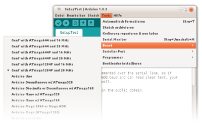
Now you can start Arduino IDE again. If you had success you'll see six additional entries in the Board menu:
Note: Gen7 Arduino IDE Support before v2.0 doesn't know about the ATmega1284P, so you get 4 additional menu entries only.
Bootloader Upload
This section only applies if you have a blank, factory fresh ATmega on your board. Friendly RepRap electronics vendors will ship with a bootloader already uploaded, so you don't need a programmer and can skip this section. Also, if your bootloader works, there's never a need to replace it, regardless of which firmware you want to upload. Firmware and bootloader are entirely independent.
Uploading the bootloader requires a programming device. Dedicated programmers usually cost some $20 to $30. For an overview, including free alternatives like parallel port bit banging, see AVR Programmers.
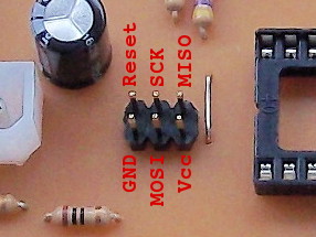
The pinout of the ICSP connector of RepRap electronics is the same as the one on Arduinos, so you can use the same programming devices, wiring and connectors. This picture shows a Gen7 v1.5 connector for re-confirmation:
Note: This process can be done on a partially populated board. Only the power supply, oscillator, reset switch and ISP connector are required. Stepper drivers, MOSFETs and such stuff are redundant.
How to proceed:
- Disconnect all connectors, including the power supply.
- Insert the ATmega into its socket. Make sure you orient it correctly. On a Gen7, the groove on the package is inserted at the heater connector side of the PCB, the part markings can be read when viewing the ATmega from the ATX20/24 connector side.
- Connect your programmer to the 6 pin ISP connector. Verify it is plugged in the right direction.
- Plug in the PC side of the programmer.
- Re-connect the power supply, do not turn it on yet.
Note: On a Gen7, the pins used for the programmer are shared and can conflict with an extension board, so if you have one, unplug it while using the programmer or be sure there is no conflict. On a Gen7 v1.2 and before, the pins are shared with some endstop connectors, so unplug the endstops while programming.
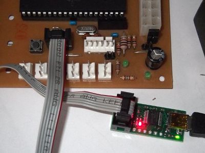
Now you should see something like this - the red LED indicates the Board is still without power:
Programming the bootloader using the command line
- Have your Arduino IDE prepared, as explained above. All six variants of the bootloader .hex files can be found inside one of the installed folders.
- Switch on your power supply. On a Gen7, at least the yellow LED should illuminate.
- Open a terminal and change directory into Arduino IDE's folder. All required tools are there, even if you haven't installed them system-wide.
General
The HEX files with bootloaders can be found in the unpacked IDE Support package, in the Gen7/bootloaders/Gen7 folder. Choose the version for your MCU and crystal frequency (e.g. bootloader-1284P-20MHz.hex). Here we assume the support package is installed inside the Arduino package already.
We're going to use these fuse settings here:
LFUSE = 0xF7
HFUSE = 0xDC
EFUSE = 0xFC
These have shown to be reliable.
Linux
The following sequence was done on Linux and should apply similarly on other OSs.
cd hardware/tools  # this is where you find the tools inside the Arduino IDE directory
./avrdude -C ./avrdude.conf -c ?  # find your programmer, e.g. "avrispv2"

### For the ATmega644:
# write fuses
./avrdude -C ./avrdude.conf -c <your programmer> -p atmega644 -P /dev/ttyACM0 \
    -B 5 -U lfuse:w:0xF7:m -U hfuse:w:0xDC:m -U efuse:w:0xFC:m
# upload bootloader
./avrdude -C ./avrdude.conf -c <your programmer> -p atmega644 -P /dev/ttyACM0 \
    -B 1 -U flash:w:../Gen7/bootloaders/Gen7/bootloader-<your variant>.hex
# lock the bootloader
# this gives an expected "verification error 0xcf != 0x0f"
./avrdude -C ./avrdude.conf -c <your programmer> -p atmega644 -P /dev/ttyACM0 \
    -B 1 -U lock:w:0xCF:m

### For the ATmega644P:
# like above, but swap "-p atmega644" with "-p atmega644p"

### For the ATmega1284P:
# like above, but swap "-p atmega644" with "-p atmega1284p"

### For an USB programmer:
# like above, but swap "-P /dev/ttyACM0" with "-P usb"
Watch your programmer blinking for a few seconds and you're done. Note that if you're using an Arduino board as a programmer, you may need to add the flag "-b 19200" for it to work correctly. 9/19/15: avrdude protects the fuses from accidental writes. In order to disable this feature you will need to add the -u flag (lowercase!). If using a hacked parallel cable, the programmer is dapa.
Windows
On Windows, you'll have to find out which COM port your board is connected to. Or simply try COM1 ... COM8 until it works. Similarly to the above, the commands on Windows are:
cd hardware\tools\avr\bin
avrdude -C ..\etc\avrdude.conf -c ?  # find your programmer, e.g. "avrispv2"

### For the ATmega644:
# write fuses
avrdude -C ..\etc\avrdude.conf -c <your programmer> -p atmega644 -P COM1 \
   -B 5 -U lfuse:w:0xF7:m -U hfuse:w:0xDC:m -U efuse:w:0xFC:m
# upload bootloader
avrdude -C ..\etc\avrdude.conf -c <your programmer> -p atmega644 -P COM1 \
    -B 1 -U flash:w:..\..\..\Gen7\bootloaders\Gen7\bootloader-<your variant>.hex
# lock the bootloader
# this gives an expected "verification error 0xcf != 0x0f"
avrdude -C ..\etc\avrdude.conf -c <your programmer> -p atmega644 -P COM1 \
    -B 1 -U lock:w:0xCF:m

### For the ATmega644P:
# like above, but swap "-p atmega644" with "-p atmega644p"

### For the ATmega1284P:
# like above, but swap "-p atmega644" with "-p atmega1284p"
Watch your programmer blinking for a few seconds and you're done.
Programming the bootloader using the Arduino IDE
Many programmers don't use the USB protocol directly, but an internal USB-TTL converter. So far there was no luck uploading the bootloader with these from Arduino IDE's graphical user interface.
Debugging hint: Arduino obviously doesn't attempt to use the "-B 5" flag when writing fuses onto a factory fresh chip. This is needed if the programmer was set to a higher speed earlier, as an ATmega running at 1 MHz (factory default) can't keep up with 115200 baud.
Arduino IDE and a USBtinyISP
- Disconnect all connectors, including the power supply.
- Remove jumper No.3 from the USBtinyISP programmer.
- Plug in the USB cable to the USBtinyISP.
- Plug the 6 pin cable from the USBtinyISP into your Gen 7 Electronics. Again, watch out for insertion of the plug the right way.
- Re-connect the power supply and turn on.
- Start up Arduino IDE.
- Select the correct ATmega chip you are using in the Tools->Board menu.
- Do not select a COM/Serial port.
- Select Tools->Burn Bootloader->w/USBtinyISP
The USBtinyISP red LED should light up. It will take a minute or two to program the chip When it is done, the IDE will tell you it has completed and the red LED will turn off.
Bootloader Troubleshooting
Contrary to popular belief, the bootloader has zero influence on firmware behaviour. Bootloader and firmware are entirely independent from each other. They can even communicate at different baud rates. Accordingly, as long as you can upload a firmware, there's no need to replace the bootloader.
- If avrdude (or Arduino IDE, which uses avrdude) reports "wrong signature", you've choosen the wrong variant of the bootloader. ATmega644, 644P and 1284P all have, while being pin and function compatible, different signatures. Make sure to choose the right variant of the bootloader.
- A bootloader compiled for 16 MHz won't work on an ATmega running at 20 MHz and vice versa. Again, make sure to choose the right variant.
- If firmware upload attempts result in timeout errors, no communications happens at all. In addition to the previous point, this can be caused by a missing auto-reset. To activate the bootloader manually, hit and release the reset button shortly (max. 3 seconds) before uploading. Arduino IDE starts uploading as soon as it shows the size of the compiled firmware.
- If all attempts with the bootloader fail, but you have a programming device, you can always upload a firmware with the programmer directly. Works just the same way you upload with a bootloader, just replace the serial connection with the one for the programmer. An eventually existing bootloader gets erased in this case.
Specials
One user had a power supply delivering just 4.5 volts in standby. That's tight, because at 4.3 V the brown-out detector jumps in and resets the board.
To deal with this, you can change the extended fuse from 0xFC to 0xFD. This sets the brown-out detector's trigger level lower, to 2.7 V. While the ATmega will run out of specification for short periods of time, then, this is obviously better than random brownout resets or no brown-out detector at all.
References
- AVR Fuse Calculator
- Check fuses and other ATmega properties with:
./avrdude -C ./avrdude.conf -c <your programmer> -p atmega644p -P /dev/ttyACM0 -n -v
- How to write the bootloader onto Arduinos
- Bootloader half the size of Arduino's/Sanguino's
- About programming with direct USB programmers like the USBTinyISP. Hint: you need to use "sudo" or write a rule in /etc/rules.d.


