RAMPS 1.4
|
English • العربية • български • català • čeština • Deutsch • Ελληνικά • español • فارسی • français • hrvatski • magyar • italiano • română • 日本語 • 한국어 • lietuvių • Nederlands • norsk • polski • português • русский • Türkçe • українська • 中文(中国大陆) • 中文(台灣) • עברית • azərbaycanca • |
Vitamin

| RepRap Arduino Mega Pololu Shield
Arduino MEGA based modular RepRap electronics. | |
| Wikipedia | none |
Contents
- 1 Design
- 2 Wiring
- 3 Firmware and Pin Assignments
- 4 Assembly
- 4.1 Component Soldering
- 4.2 Required Tools
- 4.2.1 Shield Assembly
- 4.2.1.1 C2 - 100nF capacitor
- 4.2.1.2 LED1 - Green LED
- 4.2.1.3 LED2, LED3, LED4 - Red LED
- 4.2.1.4 R13, R14, R15 - 10 Ohm resistor
- 4.2.1.5 R12 - 1K resistor
- 4.2.1.6 R23, R24, R25 - 1.8K resistor
- 4.2.1.7 R1, R7, R11, R21, R22 - 4.7K resistor
- 4.2.1.8 R16, R17, R18, R19, R20 - 10K resistor
- 4.2.1.9 R2, R3, R4, R5, R6, R8, R9, R10 - 100K resistor
- 4.2.1.10 C1, C5, C8 - 10uF capacitor
- 4.2.1.11 C3, C4, C6, C7, C9, C10 - 100uF capacitor
- 4.2.1.12 Reflow SMT soldering
- 4.2.1.13 Top pins
- 4.2.1.14 Driver sockets
- 4.2.2 Pololu carriage
- 4.2.3 Pre-Flight Check
- 4.2.1 Shield Assembly
- 5 THERMAL DESIGN FLAWS?
- 6 Hacking (archived information and notes)
- 7 Where to get
- 8 Modifications, hacks and add-ons
Design
In RAMPS 1.4 the capacitors and resistors are now surface mount (SMD) components. This provided more space for more passive components, as well as headers. This does add another set of steps to the assembly process, but we stuck with larger sizes to make it fairly painless.
This board is mainly a 12V board, but could be modified to work at 24V.


Source
| FILE ID# | TYPE | DESCRIPTION | DOWNLOAD |
|---|---|---|---|
| File:ArduinoMegaPololuShield.zip | Eagle Files | These are the files you need to make the board.(Use the File: link to the left to access older versions of the file.) | media:ArduinoMegaPololuShield.zip |
| File:RepRapjr.lbr | Eagle Libraries | The components used in this board are here. see Eagle_Library | media:RepRapjr.lbr |
Variations
There are multiple boards all based on the RAMPS 1.3/1.4 design with minor variations in form factors and components, for example Prusa, Ultimaker and others. Other incarnations combined the components of the Arduino ATmega and the RAMPS into a single board, some using ATMega128. They may have different power/rating capabilities but the basic structure and electrical behavior is very similar and we describe them as RAMPS compatible, in fact most boards in firmwares like Marlin are treated as derivate of RAMPS.
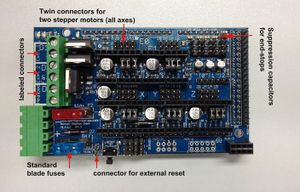
RAMPS 1.4.2, Standard blade fuses instead. Thicker cooper traces. Suppression caps added to each end-stop.
GermanRepRap GitHub Repo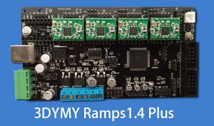
Ramps1.4 Plus, Integrated ATMega 2560
Ramps1.4 Plus Wiki
Ramps 1.4.4, SPI support for TMC2130. Able to use single 24V source. Same form factor.
RAMPS 1.4.4 Wiki, GitHub Repo
Smart Ramps 1.4.x. Fixed microstepping, Compatible with Arduino Due.
SMART RAMPS 1.4.x Wiki
MKS Gen L V1.0, Integrates an ATmega2560 and a RAMPS 1.4 into a single board.
MKS Gen L, GitHub Repo


Wiring
This section presents the basic steps to wire an assemble RAMPS 1.4 board assuming the more common scenarios. Check the #Assembly section to learn how to assemble your own Ramps 1.4 board.
|
Once you start putting electricity into your board - even at just 12 volts - you have to take basic, common sense precautions to avoid fires. Just in case these fail, test your workshop smoke detector. |
|
Inverting polarity of cable connections or other errors wiring your board MAY destroy the board or the microcontroller. Please review all of your connections prior to turning the power ON. |
Bed
The heater element of the bed is connected to the D8 screw block. We presume that you are using a 12V bed heater (max power 120W).
A PCB bed heater rated at 120W is the commonly used with RAMPS, more advanced types are Kapton or a Silicone heater.
Notice that the bed thermistor connects to a header block of three pairs. From left to right they are labeled T0 for the first extruder, T1 for the heatbed, and T2 for a second extruder.
The bed thermistor is connected to the T1 connector. A thermistor does not have polarity so don't worry about the pin order.

| There are many factors when considering if a heatbed will work with your RAMPS board or if your heatbed will destroy your board. The first consideration is the MOSFETs of your board. Your theoretical limit is 11A at 120V, which is about 120W that a heater can consume. If you get a heater that draws more power it will kill your MOSFETs. Many RAMPS clones use MOSFETs that are not rated for 11A or even the average 8A you will see on a 12V heatbed. Second is the actually amperage that your PSU can deliver. The heatbed should be inside the operating parameters of these two. The FET (fuses) on the boards together with the MOSFETs are the first candidates to burn out if your heatbed draws more power that the supported rating. When shopping for a heatbed consider a 120W/12V option that is well within the parameters or a traditional RAMPS 1.4 board. |
Hotend
The extruder has a heating element (heater cartridge) in the heating block that connects to the screw terminal labeled D10. The heating element must be 12V and consume an average of 2.5 amps. The temperature of the extruder is monitored by a thermistor also installed in the heat block. The thermistor is connected in the terminal labeled T0 (uses pin A15 in Arduino). (The thermistor does not have a polarity.)

Connect the extruder fan to the screw terminal labeled D9

Endstops
| Pay attention when connecting the endstop to the RAMPS 1.4. Before you continue we suggest you read our wiki page on mechanical endstops. The RAMPS 1.4 offers no pull-up circuits, current limiting resistors or other protections. Wiring improperly an endstop that uses 5V may damage an IO port on the ATmega 2560 or the Arduino itself, this is a particular issue with clones of the Arduino ATmega2560. |
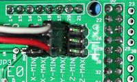
The endstops are the switches that tell the firmware when one of its axis (X, Y, Z) has reached either (or both) its minimum or maximum limit. In the board you will find six 3 pin connectors labeled (from left to right) X-MIN, X-MAX, Y-MIN, Y-MAX, Z-MIN, and Z-MAX. While you may connect both endstops for an axis the common setup is to use only one per axis. (Note firmwares implements software endstops for the opposite side using the dimensions on the build area of the printer.)
To simplify the setup of the firmware it is easier to only use the minimum pins of each axis. The minimum is also know as the home location of your axis, on our traditional cartesian FDM printers we said that the end stop for the Z axis is in the bottom end of the frame, for the X axis is to the left of the frame and for the Y axis is somewhere near the back. (Note: all of this can be configured at will but requires more changes in the firmware. Check this excellent page explaining endstops from the Marlin Firmware guys.)

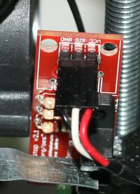
In the above figure we illustrate two common mechanical endstops that you will find. Check the wiki for mechanical endstops for more e info.

You have endstops with 3-pin connectors. Now days when shopping online is very common to find 3-pins endstops with leds, mainly due to all the Ender 3, CR-10 and similar clones that use them.
Is also common to find endstops with 2-pin connector or using only 2-wires (even if the connector has 3-pins). This is also the case when you wire your endstops directly, in which case only the COMMON and NC pins of the switch are used.
From top-to bottom you will notice that for each axis the first pin is the Signal S, the second is GND, and lastly the 5V pin. In a two pin connection the + pin is NOT used.
When wiring a 2-pin endstop the NC pin is connected to GND (-) on the board. The COMMON pin (marked as C or S) is connected to the S on the board. Usually the endstop will have their pins identified.
| When wiring a 3-pin endstop is best not to make assumptions about the pinout on the endstop, check for markings on the PCB, read the manufacture's information or use a multimeter to identify the pins. |
Once you have figure out the type of endstops all that is left to do is to plug the corresponding connector for each axis using minimum pins in the board.
| Using a switch that supports a NC (normally close) state is the preferred choice since it serves as a good safety feature. In case of a broken cable or broken switch or other damage, the circuit will open and the firmware can execute its expected fail-safe. |
| Setting up Marlin when using a Mekerbot Endstop or Pull-up-Resistors: 1. Comment the constant ENDSTOPPULLUPS in configuration.h to disable the built-in pull-up resistors. 2. Change the value of the constants X_MIN_ENDSTOP_INVERTING, Y_MIN_ENDSTOP_INVERTING, Z_MIN_ENDSTOP_INVERTING to true. |
See also
Drivers
The board allows up to 5 independent motors using stepper motor drivers which today is mainly drivers using the board design of Pololu like the A4988, the DRV8825 or even TMC2130.
| If your Pololu driver do not have the header 1x8 pin headers you need assemble the driver. The pins go in from the bottom to the top side (side with potentiomer and chip). When soldering the pins take pauses to avoid damaging the header from the heat buildup. If you bought a kit with one 16 pin header you have to cut it in half to make two 1x8 headers. The heat-sink goes on the largest chip on the top side using the provided pad of double-sided adhesive. |

Before installing the driver you need to set up the jumpers corresponding to each stepper to set the steps. These jumpers define the microsteps for that particular driver. For A4988 setting all the jumpers will set the micro stepping to 1/16 of a step. For a DRV8825 setting the last jumper will enable 1/16 micro stepping.
A 1/16th is a common value for Pololu drivers. The micro-steps that you select affect the steps per revolution which in term is used to compute the steps per unit in your firmware. The general formula is Steps per Unit = Motor Steps per Revolution / Idler Teeth / Belt Pitch. See the Triffid Hunter's Calibration Guide... |
See Stepper Motors for info on motors.
| Some Ramps 1.4 clones have the jumper pads connected on the PCB due to manufacturing errors. You will not be able to change the micro-steps using the jumpers unless you cut the pads off. In many case is set to 1/16 micro-steps. Check your board with a multimeter to see if any pins have continuity when the jumper is off. |
| Some notes on TMC2130: Getting TMC2130 stepper drivers to work on a RAMPS 1.4 board requires modifications to the board. TMC2130 stepper drivers are configure by software using SPI. TMC2130 drivers require the pins from AUX02 and AUX-3 to be available if for example you have an SD Card or and LCD, chances are that you won't be able to setup the SPI interface for the TMC2130. |
| The trimpot on the stepper drivers controls the current limit. Turn it all the way down (counter clock wise) and back up 25%. Be careful to not force the trimpot, it is delicate. You will need to fine tune the current limit later. Note that it is always giving the motors that much power, even when not moving, so if your stepper motor drivers are getting hot, you may want to turn it down slightly. |
| Incorrectly inserting stepper drivers will destroy your electronics and cause a fire risk. Always make sure power and USB is disconnected when removing or adjusting stepper drivers. Always make sure to insert drivers in correct orientation and in the socket correctly. Below is an image of both driver inserted into the RAMPS board, in the correct orientation. The green units are Pololu stepper drivers, the purple are DRV8825 based drivers. |

See also
Motors
A RAMPS 1.4 board using traditional Pololu drivers provide from 1A to 1.2A of current and about 4V to a NEMA motor. The force a motor can produce is mainly measure by its holding torque (For example 3.2 kg-cm, You will also find this in Newtons or oz-in)
For most cartesian printers designed with RAMPS 1.4 perform quite well with motor that can provide 44 N·cm is quite enough for most designs.
The force it can produce. The main metrics for this is the holding torque (For example 3.2 kg-cm, You will also find this in Newtons or oz-in). For most designs an average of 44 N·cm is enough force to handle your everyday prints.
The steps of a motor is how accurately it can move. This is given in degrees per step or steps per revolution. For example in 3D printing an average NEMA17 motor used is 1.8 or 0.9 degrees with 200/400 steps per revolution. If a motor makes a 1.8 degree rotation in one step, then to complete one revolution (that is 360 degrees in a circle) it will take 200 steps. Most common NEMA 17 motors are 1.8 degree steppers.
Check this wiki for more info on motors compatible with Ramps 1.4.
| NEMA: A traditional 3D printer motor is a NEMA-17 (or NEMA-23). NEMA defines the dimensional specifications of a motor's mounting face, thats the spacing of screws, the size of the opening and the size of the screws. The depth, width and other shapes and features are at the discretion of the motor manufacturer. So NEMA only guarantees that a particular NEMA motor will mount a specific mount designed for it, while actual clearance to the sides and back will also have to be considered when selecting a motor.
Usually in the maker space and 3DPrinting a NEMA motor is a short hand to refer to a bi-polar (2 phases motors) stepper motor with micro-stepping. Read more about stepper motors... |
A motor will have 4 cables either directly attached or as a ribbon that has a (JST-XH) six pin connector in the motor. The other end of the connector will be a 4 pin header that attaches to the RAMPS board. (From the six pins of a motor only four are used on the connector.)

Since the motor has two coils (2 phases motors), each coil has two pairs of cables. Like shown on the above picture the trick is to identify what pin in the motor corresponds to a pair. The illustration shows two common combinations, we call them straight and cross. The straight has the pins for the coil in order and the cross switches the two in the middle.
The important thing of wiring a motor is to get the pin combination for each coil and wire each coil to your motor driver or control board.
| The colors of the cable can be arbitrary and should not be used as a reference to identify the coils. |
The other thing with the two cables in a pair is their polarity. The polarity tells the direction of the spin. There is not such thing as wrong direction instead the direction is dictated by how is the motor used and the control board. For this reason in many motor diagrams you will NOT see polarity specified as is left for the implementation of the design to select the default direction.
| If you don't have the pintout of the coils the main sign of a motor thats wired incorrectly is that it will vibrate/shake and will not turn. This is because both phases are spinning in the opposite direction locking the spin. Which pair connects to which coil does not matter as long as you have the two cables of one pair going to one coil. A common error is to have one cable from one pair going to the other coil and vice-versa.
Using a multimeter in continuity (resistance/diode test mode) you can test the combinations of pins until you find the pair that belongs to one coil. In continuity test you will have a low resistance value, some multimeters beep or read "short/closed" to indicate when you found a pair. Use the first picture as reference to check if you have a straight or crossed pinout. Hint If you are swapping a motor in a printer or equipment already wired, then check both ends to see which are the pairs, use the picture "Common Coil Combinations" for reference. If your new motor came with a cable then compare the motor end of the new and old connector to quickly tell if its cross or straight. Usually black/green are in one side and blue/red in the other (don't mind the order of the pairs), if you see one cable from one of these two pairs swap in the middle two pins, chances is that you have a crossed connector for your motor. |
| As mentioned before as long as the pairs for the coil are correct you don't have to worry much about which pair goes to which coil (they both do the same job). As for polarity (step direction) with many 3D printers the connector on the board can be easily be flip to reverse the the polarity if the motor spins in the wrong direction. The only thing that matter is that the two wires for a particular pair connect to one coil in the motor and that you do not have one cable for one pair going to the other coil (mix them). |
| In most controller boards in 3D Printers (and GRBL Shields) flipping the connector changes the spin direction (polarity +/-). If flipping a connector around does not fix the spin direction you may need to rewire the connector using a tweezer or needle to loose the pins from the connector and flip the order. Also in many 3D printing firmwares (eg Marlin) changing the direction as desired is as simple as changing a configuration value. In CNC shields for GRLB you usually find a jumper to change the direction of an axis. |

Finally connect each of the motor's 4-pin connector to the corresponding axis as shown in the above illustration.
| Triffid Hunter made an excellent calibration guide that is quite valuable when configuring your firmware. Check the guide here.
MatterHackers also have an excellent guide for Marlin here. |
Aux Fan
Auxilary 12V Fan, always on.

Power Supply

Connect the 12V power cables to the positive end (+) on the board. In your Power Supply (PSU) these cables may be yellow or red and are usually labeled V+ or 12V. The black cable is negative/ground and is usually labeled V- or COM. Always check the label on the power supply for actual cable details or see the manufacturer's manual.
| Reversing +/- or otherwise incorrectly connecting power can destroy your electronics and cause a fire hazard. |
The board has two pairs of connectors for power, one labeled 11A and the other 5A, both of these pairs are 12V connections. The 11 amps pair is used to power the heated bed. The 5 amps source is used to power the board, the rest of the printer's components and the Arduino board.
| 24V Visit this detailed guide on using 24V on a RAMPS 1.4 board. |

Your power supply should be able to deliver 16 amps, is ok if it delivers more. The generic S360-12 power supply is commonly used in 3D printers and provide about 30A/360W. Other variants are the S-480 and S-600 for 480W and 600W respectively.
| The heater block on the extruder shares the 5A source, make sure that the amperage/current drawn by additional extruders can be supported by the board. |
| The barrel connector, on the Arduino MEGA, will NOT power RAMPS and will not provide power to the stepper motors, heated bed, etc. |
See also
Power for the Arduino Mega board

The RAMPS 1.4 has a 1N4004 diode labeled D1 which allows 12V to feed and power the Arduino Mega 2560 board. This diode is installed in most pre-assemble boards, thus the Arduino board is powered by the Ramps by default.
When the RAMPS is not powered or if the diode is not installed or cut/removed, the Arduino gets its power from USB or a power supply connected to its 2.1mm (center positive) power jack.
The Arduino provides a Vin connection to connect an external power source that can be from 7V to 12V, remember the diode D1 can not be connected if you plan to power the Arduino using its Vin.
| The Arduino Mega is not rated for voltages higher than 12V. If your board has a 1N4004 diode soldered in Diode D1 (which is the case with most assembled board), do not apply more than 12V in the 5A connector of your Ramps, refer to RAMPS 24v for more information. |
Power Supply, Details and Considerations
The PS_ON pin is intended to switch your power supply on and off. Many firmwares support pulling this pin low with M80 command to turn the power supply on, and M81 to turn it off. This behavior is desired for ATX power supplies and can be modified in firmware to support 5V high power supplies like those borrowed from an Xbox.
If you want to use PS_ON to turn on your power supply then don't use diode D1, you need your Arduino to be powered from 5Vsb otherwise when no USB is connected the PS_ON pin floats (and your power supply pulses on and off).
RAMPS is quite happy with the 12 V line from PCPowerSupply. Or you can hack up a 12V laptop power supply, or other 12 V "wall wart" power supply. Make sure that the power supply can output 5A or greater. Additional 11A may be needed for heated bed support.
The 3 pins next to the reset switch are meant to optionally connect to your PSU.
The 5V pin in that connector on RAMPS only supplies the 5V to the auxiliary servo connectors. It is designed so that you can jumper it to the VCC pin and use the Arduino's power supply to supply 5V for extra servos if you are only powered from USB or 5V. Since there is not a lot of extra power from the Arduino's power supply you can connect it directly to your 5V power supply if you have one. You can also leave this pin not connected if you have no plan to add extra servos.
Maximum Input Voltage
There are three limiting factors to the maximum voltage that you can put into the RAMPS:
- The Arduino Mega maximum input voltage
- Filtering capacitor maximum voltages
- PTC fuse maximum voltages
First, the 1N4004 diode (Diode D1) connects the RAMPS input voltage to the Arduino Mega which has a recommended maximum input voltage of 12 volts. If your board does not have this diode soldered in (or if you cut it), you will need to power the Mega through the USB connector or through a separate 5v line, but this allows a higher RAMPS voltage.
Second, most boards use 25v or 35v aluminum electrolytic capacitors (C2, C3, C4, C6, C7, C9, and C10). To be safe, you should only go to half of your rated maximum voltage -- thus if your board has 35v capacitors (code VZA) then you should use a maximum input of 17.5v. The absolute maximum voltage is determined by the Pololu servo drivers, which themselves are limited to 35V.
Third, the MF-R500 (5A) PTC fuse is rated to 30V and the MF-R1100 (11A) PTC fuse is rated to 16V. They will need to be replaced with real fuses.
Other Install Considerations
DON'T secure Arduino/RAMPS with conductive screws through both mounting holes. The screw may cut into the positive trace creating a HIGH current short.</font>
Some users suggest adding a heatsink to the Q3 MOSFET to help dissipate heat and prolong the life or replace MOSFET with one rated at higher current.
Firmware and Pin Assignments
| Note that Tesla & Tonok firmware use D9 and Sprinter, Marlin, and Johnny/Tonok use D10 for the extruder hot end. |
| ROBO3D R1 and R1+ Ramps boards have a connector labeled "FAN9". This connector is actually connected to Arduino's pin 9 like regular RAMPS and it corresponds to the D9 connector on a RAMPS board. On R1+ board the extruder heater is connected to the plug labeled D9. This connector corresponds to the original D10 of RAMPS board and still responds to Arduino's pin 10. |
Marlin
The Marlin Firmware is a port of the Sprinter and Grbl projects. Beyond its popularity it also provides out of the box support for RAMPS 1.4 boards.
As of 2012 Marlin has built-in support for RAMPS 1.3 and Ramps 1.4 boards. Marlin's Firmware up to version 1.1.9 and even version 2 compile with ease using new version of the Arduinos IDE. Compiling a firmware older than 1.1.x require changes to the code or to use an older IDE version.
In your configuration.h you tell Marlin that you are using a Ramps 1.4 board. To see which boards are supported open "boards.h".
configuration.h// The following define selects which electronics board you have.
// Please choose the name from boards.h that matches your setup
#ifndef MOTHERBOARD
  #define MOTHERBOARD BOARD_RAMPS_14_EFB
#endif
The constant BOARD_RAMPS_14_EFB defines the pins for a stock RAMPS 1.4 with an extruder, a heated bed and a fan.
If you have a RepRapDiscount Smart Controller the you need to uncomment this line in your configuration.h so that it reads like this:
configuration.hdefine REPRAP_DISCOUNT_SMART_CONTROLLER
For the RepRapDiscount Full Graphic Display (DOT Matrix 128x64) you need to uncomment this line in your configuration.h so that it reads like this:
configuration.hdefine REPRAP_DISCOUNT_FULL_GRAPHIC_SMART_CONTROLLER
More instructions on installing Marlin are available here.
SRAMP
The SRAMP Firmware is a fork of Marlin v1.1.9 exclusively tailored Mendel/Cartesian printers using 8Bit Microcontrollers. The firmware sports a new GCODE parser and aims to make it easier hobby builders to add features (LCD, SD, etc).
Sprinter
The Sprinter Firmware is no longer under active development.
Working preconfigured Sprinter firmware can be downloaded here: File:UltiMachineRAMPS1-4Sprinter.zip. Mechanical is in the folder ending with ME, optical endstop firmware is in the folder ending in OE.
Pins
Others (Need pins set in Firmware as below):
- mechanical endstops (now the default ultimachine.com option) require #define OPTO_PULLUPS_INTERNAL 1 to be added to configuration.h if not there by default.
Here are the pin definitions for this board.
// For RAMPS 1.4
#define X_STEP_PIN         54
#define X_DIR_PIN          55
#define X_ENABLE_PIN       38
#define X_MIN_PIN           3
#define X_MAX_PIN          -1 //PIN 2 is used

#define Y_STEP_PIN         60
#define Y_DIR_PIN          61
#define Y_ENABLE_PIN       56
#define Y_MIN_PIN          14
#define Y_MAX_PIN          -1 //PIN 15 is used

#define Z_STEP_PIN         46
#define Z_DIR_PIN          48
#define Z_ENABLE_PIN       62
#define Z_MIN_PIN          18
#define Z_MAX_PIN          -1 //PIN 19 is used

//extruder 1
#define E0_STEP_PIN        26
#define E0_DIR_PIN         28
#define E0_ENABLE_PIN      24

//extruder 2
#define E1_STEP_PIN        36
#define E1_DIR_PIN         34
#define E1_ENABLE_PIN      30


#define SDPOWER            -1

//ChipSelect, Hardware SS Pin on Mega, 10 for Arduino Boards, always kept as output
#define SDCS_PIN           53
#define SD_DETECT_PIN 	   -1 //currently not implemented


#define LED_PIN            13

#define FAN_PIN            9

#define PS_ON_PIN          12	//ATX , awake=LOW, SLEEP=High
#define KILL_PIN           -1

#define HEATER_0_PIN	10  // Extruder Heater
#define HEATER_1_PIN	8

#define TEMP_0_PIN		13   // ANALOG NUMBERING
#define TEMP_1_PIN		14   // ANALOG NUMBERING
Bill of Materials
| ID | Description | Quantity | Part Number | Reichelt Order Number | Digikey Part Number (Description) |
|---|---|---|---|---|---|
| U1 | Arduino Mega or clone | 1 | 2560 or 1280 | 1050-1018-ND(BOARD MCU MEGA2560) | |
| U2,U3,U4,U5 | Pololu stepper driver boards or clones | 4 | A fifth one can be used for a 2nd extruder or extra axis | N/A | |
| C2 | 100nF capacitor (0805)(> highest planned voltage) | 1 | 311-1141-1-ND(CAP CER 0.1UF 25V 10% X7R 0805) | ||
| C1,C5,C8 | 10uF capacitor (153CLV-0405)(>5V) | 3 | 399-6724-1-ND(CAP ALUM 10UF 25V 20% SMD) | ||
| C3,C4,C6,C7,C9,C10 | 100uF capacitor (153CLV-0605)(> highest planned voltage) | 6 | 399-6726-1-ND(CAP ALUM 100UF 16V 20% SMD) | ||
| R1,R7,R11,R21,R22 | 4.7K resistor (0805)(1%) | 5 | RHM4.70KAECT-ND(RES 4.70K OHM .4W 1% 0805) | ||
| R2,R3,R4,R5,R6,R8,R9,R10 | 100K resistor (0805) | 8 | RHM100KAECT-ND(RES 100K OHM .4W 1% 0805) | ||
| R12 | 1K resistor (0805) | 1 | RHM1.00KAECT-ND(RES 1.00K OHM .4W 1% 0805) | ||
| R23,R24,R25 | 1.8K resistor (0805) | 3 | 311-1.80KCRCT-ND(RES 1.80K OHM 1/8W 1% 0805) | ||
| R16,R17,R18,R19,R20 | 10K resistor (0805) | 5 | P10.0KCCT-ND(RES 10.0K OHM 1/8W 1% 0805) | ||
| R13,R14,R15 | 10 ohm resistor (0805) | 3 | 541-10.0TCT-ND(RES 10.0 OHM .33W 1% 0805) | ||
| Q1,Q2,Q3 | N-channel Mosfet | 3 |
-STP55NF06L Upgrade particularly for the bed: - IRLB8743PBF or for even more current |
STP 55NF06L STM IRLB 3034 |
STP55NF06L (MOSFET N-CH 60V 55A 18mΩ TO-220 @11A=+135*C )
IRLB8743PBF (MOSFET N-CH 30V 78A 3.2mΩ TO-220 @11A=+24*C) IRLB3034PBF (MOSFET N-CH 40V 195A 1.7mΩ TO-220 @11A=+13*C) |
| D1,D2 | Diode | 2 | 1N4004 | 1N 4004 | 1N4004FSCT-ND (DIODE GEN PURPOSE 400V 1A DO41) |
| F1 | PTC resettable fuse (30V, Hold5A, Trip10A) | 1 | MF-R500 | PFRA 500 | MF-R500-ND (FUSE PTC RESETTABLE 5A HOLD) |
| F2 | PTC resettable fuse (Hold11A) | 1 | MF-R1100 | RGEF1100-ND (POLYSWITCH RGE SERIES 11.0A HOLD) | |
| J2 | D8-D10 Outputs // 6 position screw terminal (min 11A per contact) OR Jack/Plug connector pair | 1 | 282837-6 | AKL 101-06 | WM7857-ND (CONN TERMINAL BLOCK 6POS 5.08MM)
OR 1935200 (TERM BLOCK PCB 6POS 5.0MM) OR 1x 609-4284-ND & 1x 609-4218-ND. May prevent overtemp events |
| LED1 | Green LED (0805) | 1 | L62505CT-ND(LED GREEN DIFF 0805 SMD) | ||
| LED2,LED3,LED4 | Red LED (0805) | 3 | L62501CT-ND(LED HI EFF RED DIFF 0805) | ||
| S1 | Push button switch | 1 | B3F-3100 | TASTER 3305B (should fit footprint also, but button will overhang board edge) | 450-1648-ND (SWITCH TACT RA H=6.35MM) |
| X1 | Power jack (Plug and fixed receptacle)(Min 11A per position more is better) | 1 | MSTBA 2,5 and MSTBT 2,5 (5.04mm spacing 4 connector) | WM7847-ND (CONN HEADER 4POS 5.08MM R/A TIN) & WM7953-ND (CONN TERM BLOCK 4POS 5.08MM R/A)
OR 1935187 (TERM BLOCK PCB 4POS 5.0MM) | |
| 2 x 3 pin header | 8 | 961206-6404-AR | 3M9459-ND (CONN HEADER VERT DUAL 6POS GOLD) | ||
| 4 pin header | 5 | 961104-6404-AR | SL 1X36G 2,54 (3 of these) | 3M9449-ND (CONN HEADER VERT SGL 4POS GOLD) | |
| 6 pin header | 2 (? see this) | 3M9451-ND (CONN HEADER VERT SGL 6POS GOLD) | |||
| 2 x 18 Pin Stackable Female Header (non stackables can be used with plated through holes) | 1 | MALE: SL 2X25G 2,54 (2 of them, shortened with a saw or pliers) | S7121-ND (CONN HEADER FMAL 36PS.1" DL GOLD) - Not Stackable | ||
| 8 Pin Stackable Female Header (non stackables can be used with plated through holes) | 5 | S7041-ND (CONN HEADER FEMALE 8POS .1" GOLD) - Not Stackable | |||
| 6 Pin Stackable Female Header (non stackables can be used with plated through holes) | 1 | S7039-ND (CONN HEADER FEMALE 6POS .1" GOLD) - Not Stackable | |||
| 24 Pin Female Header * Note * | 2 | Required to carry enough current for motors | S7057-ND (CONN HEADER FMALE 24POS .1" GOLD) - Rated @ 3A / Pin | ||
| 8 Pin Female Header * Note * | 4 | Required to carry enough current for motors | S7041-ND (CONN HEADER FEMALE 8POS .1" GOLD) - Rated @ 3A / Pin | ||
| 0.1" Jumpers | 15 | A26242-ND (SHUNT LP W/HANDLE 2 POS 30AU) | |||
| Circuit Board | 1 | v1.4 | N/A |
Note * You can use Female Headers which are not the exact size, but they are hard to break/cut so in this case buy some extra! (one wasted header per cut)
A BOM for sourcing the RAMPS components from Mouser is also available in this google spreadsheet (This list is incomplete and has missing or incorrect quantities.)
Shopping lists for v1.4 [1] .
Assembly
Component Soldering
Required Tools
You must have: Solder iron, solder wire, good tweezers You really need: Solder wick, solder sucker, flux pen Optional methods use: Solder paste, hot plate or oven
Shield Assembly
| Reference board orientation is component side up, power inputs to the left. |

Soldering RAMPS 1.4 includes both surface mount and through hole soldering.
The surface mount can be done a few ways. Since all the SMT components on this board are large 2 pad parts you can do pin by pin soldering pretty easy with normal soldering equipment. Start by putting a small amount of solder on one pad. If you have flux, coat the soldered pad. Use the tweezers to hold the component down in position and heat the solder to tack the component into place (make sure the entire solder blob flows so you don't get a cold solder). Then solder the other pad. Also popular is using solder paste for pad by pad soldering, Oven Reflow (need link), and HotplateReflowTechnique
Solder the SMT components first. Then the PTH on top of the board. Finally solder the pin headers on the bottom.
C2 - 100nF capacitor

This can be placed in any orientation.
LED1 - Green LED

Place these with the end having green dots away from the + mark on the PCB.
LED2, LED3, LED4 - Red LED

Place these with the end having green dots away from the + mark on the PCB.
R13, R14, R15 - 10 Ohm resistor

These can be placed in any orientation.
R12 - 1K resistor

These can be placed in any orientation.
R23, R24, R25 - 1.8K resistor

These are marked 1K on the PCB, but we are using larger ones to accommodate higher voltages. These can be placed in any orientation.
R1, R7, R11, R21, R22 - 4.7K resistor

These can be placed in any orientation.
R16, R17, R18, R19, R20 - 10K resistor

These can be placed in any orientation.
R2, R3, R4, R5, R6, R8, R9, R10 - 100K resistor

These can be placed in any orientation.
C1, C5, C8 - 10uF capacitor

These must be placed in the proper orientation. The board has the foot print of the components printed on it. The rounded corners on the base of the capacitor must line up with the white print on the PCB.
C3, C4, C6, C7, C9, C10 - 100uF capacitor

These must be placed in the proper orientation. The board has the foot print of the components printed on it. The rounded corners on the base of the capacitor must line up with the white print on the PCB.
Reflow SMT soldering


If you are doing oven or hot plate method, now is the time apply heat (add links here). If you used a solder iron, you have probably already soldered all these components.
Make sure to inspect the SMT soldering at this point since it will be harder to rework after the headers are on top.
Top pins

Solder 1 1x6, 6 1x4, and 7 2x3 pin headers on top of the board. The long post should be standing up to take a connector. Solder one leg on each one to tack them into place. Then re-heat the joint and push on the component until it is perfectly situated. Then you'll want to solder the rest of the leads. You will get burnt if you touch the other side of the pin you are soldering.
If you want to use the extra pin outputs, now is the time to solder on the rest of the headers.
Driver sockets

Place the female headers for the stepper drivers on top of the board. You can use the 1x8 and 1x6 pin headers to jig them straight. Turn the board over and solder these pins.
Pololu carriage

This section assumes you are using Pololu, but there are other options. Insert two 1x8 pin headers into the board. If you bought a kit with one 16 pin header, simply cut it so that you have two 1x8. Make sure that the side with the labels has the long ends of the posts, and the side you want to solder is the side with the heat sink. Doing this backwards will cause you not to see the labels and will most likely not fit. Remember to apply a heat-sink to the largest chip on the back.
Insert the motor boards with the potentiometer to the right side (furthest from the power connectors).
D1, D2 - Diodes

These must be placed in the proper orientation. The band on the diode must be turned the same way as the mark on the board.
Definitely solder D2 in. D2, F1, and F2 are shown installed here.
D1 should only be installed if the 5A rail is powered by 12V. It can be omitted and the Arduino will be powered from USB. You will want D1 installed if you add components to print without a PC. To reiterate, D1 MUST be omitted if you are powering the 5A rail by more than 12V, or the power is not absolutely clean, otherwise you may damage your ramps.
F1 - MFR500 Fuse
This is the smaller yellow fuse. This can be placed in any orientation. When soldering the fuses it is best to use a piece of 3mm filament or something similar to keep the ceramic coating on the pins from blocking proper solder along the through hole.
Since the fuses are the tallest parts, it is simpler and more convenient to solder them last. From this point on, solder the rest of the RAMPS in order of bottom pins, reset switch, terminals, mosfets and then fuses.
Bottom pins


Place these on the bottom of the board with the long post out to plug into the Arduino MEGA. You can plug them into the MEGA to hold them in place while you solder. Do not overheat the pins while in Arduino or you may damage its connectors.
Reset switch

This can only be oriented in one direction.
Mosfet Terminal


This must be oriented where the wire holes are turned towards the edge of the board. Solder a pin on each end and make sure the component is flat on the board and solder the middle pins.
Power Terminal

This can only be oriented in one direction.
Q1, Q2, Q3 - Mosfets

These must be orientated as in the picture. The tall heat sink part of the mosfet needs to be turned the same as the mark on the board.
F2 - MFR1100 Fuse
This is the larger yellow fuse. This can be placed in any orientation.
Inspection
Inspect your work. Clean any solder bridges and suspect solders.
Pre-Flight Check
If you think you may have mistakes you can install only one stepper driver during initial testing and risk only one stepper driver.
Connect the minimum endstops for X,Y, and Z
Connect Motors (Do not disconnect or connect motors while powered; if the connection is loose, this will cause the motors to misbehave and possibly kill your stepper driver.)
You may want to use this code to test all the electronics before installing any of the suggested firmwares.
Install firmware (More info below). Firmware flashing can be done without 12V power supply connected.
THERMAL DESIGN FLAWS?
The issues are:
- The Bed mosfet gets too hot!!!
- If your heatbed draws close to or just above 11A, then the polyfuse will get very hot
- There are very thin connections around key solder-pads
The Heat Bed Mosfet gets TOO HOT!!!
Solution A: Change the mosfet to something with a lower Rds-ON resistance. And is better suited to be used with 5V Gate voltages.
Solution B: Use an external power mosfet module
The poly fuse gets too hot
Solution A: Get a different Heat Bed. All Heat Bed's have a slightly different resistance, so some draw 8A some draw close to or just above 11A
Solution B: Change the polyfuse to a (car) blade fuse.
Solution C: Use an external power mosfet module
PCB Thermal design flaw!?
As there are (by 2019) many different producers of the RAMPS 1.4 board, some who have made their own changes to the design files, thus some boards have some close to critical issues. See examples below.
WARNING - THERMAL-isolation-related DESIGN FLAW IN Power handling capacity of PRODUCTION RAMPS 1.4 boards
A "thermals" design flaw has been noted in the RAMPS 1.4 Eagle CAD files. This has been confirmed by visual inspection of production boards, which consistently shows only between two and three (almost never four) thermal-isolating traces per side of the PCB, to power-carrying pins, of under a 0.5 amp carrying-capacity per trace, assuming a 1oz copper thickness.

- This image is also in error (it isn't: it's a photograph of an existing production RAMPS 1.4 board), the left two unpopulated pins on the image are for the always on fan and use very little current. So are not an issue (actually it is)
The problem may be fixed in the Eagle CAD files - for a future version of RAMPS only - by disabling "thermals" on the GND, +12V and the +12V2 Copper pour. However on existing (mass-produced) RAMPS 1.4 boards, estimating the total widths (including all thermals from all tracks on both sides of the PCB) checking with an online copper width calculator and adding up the total current, assuming a 1oz copper PCB the maximum safe current on the fuses (giving only a 10C rise in temperature of the thermal-isolation tracks) is only around 6 (six) amps and in other areas the maximum safe current (assuming the same 10C rise in temperature) is around 8 (eight) amps.
This problem may potentially be fixed on existing RAMPS 1.4 boards by augmenting the power traces with suitably-thick insulated wires with sufficient current-carrying capacity, soldering them to all the relevant pins.
A video with a full walkthrough including calculating the total track width and inputting it into a trace width current calculator is here: https://youtu.be/4Ff_XG1OPIM
Other production boards found in the wild
Top and bottom view of production 1.4 board sourced from China with power components removed.


Minimum total parallel trace with measured on the bed power rail was about 80mil, which would equate to a 4 amp safe limit using the above considerations. Board is marked with "www.bigtee-tech.com" where the "UltiMachine" and "reprap.org/wiki/RAMPS_1.4" markings are in the original 1.4 design.
Another production 1.4 board, also sourced from China.

Note the decreased isolation of the copper pours. Slikscren has the "reprap.org/wiki/RAMPS_1.4" marking but not the "UltiMachine" found on the original design.
A video quickly looking over both of the above boards.
Hacking (archived information and notes)
This section includes information on building or assembling a RAMPS 1.4 board or printer that is no longer relevant for most use cases.
Using Opto Endstops
Opto endstop build instructions can be found at Gen7_Endstop_1.3.1, and also here for reprapsource.com's instructions.
- Cut the 26awg 3 conductor cable into 3 length.
- Note: you may want to wait until you've built your machine to cut the cables to the perfect length.
- crimp and solder a female connector to the ends of each wire. (solder not necessary with proper crimp tools)
- use the 2.54mm 1x3 housing.
- Connect at least the minimum endstops.
- Cut the 26awg 3 conductor cable into 3 length.


| RAMPS End | ||
| SIG (S) | White | Top pin |
| GND (-) | Black | Center pin |
| VCC (+) | Red | Lower pin |
| Endstop End | |
| VCC (+) | Red |
| SIG (S) | White |
| GND (-) | Black |
Where to get
- StaticBoards Spain Premium Assembled Board, Toshiba TK72E12N1 Mosfet, 15A Molex (Validated 31MAR2021) (Not in stock)
- reprapworld.com Blank PCBs (Validated 31MAR2021)
- reprapworld.com RAMPS 1.4 Kits (Validated 31MAR2021)
- Thingibox Assembled Board, (Validated 31MAR2021)
- Keyestudio Full Kit (Validated 31MAR2021)
- Keyestudio Assembled Board, Amazon Store (Validated 31MAR2021)
- Keyestudio Assembled Board, Ebay Store (Validated 31MAR2021)
- He3D Assembled Board (Validated 31MAR2021)
- RepRap.PT Portugal (Validated 31MAR2021)
- RepRap.me Denmark (worldwide shipping)
Modifications, hacks and add-ons
Using 24v on RAMPS
Details can be found on this page http://reprap.org/wiki/RAMPS_24v
Adding LEDS to RAMPS
Details can be found on this page http://reprap.org/wiki/RAMPS_LEDs
BT Extension
- main article: jy-mcu
Using a 'JY-MCU' (vendor Shenzhen Jiayuan Electronic Co.,Ltd.) Bluetooth modules (HC03, HC05, HC06 chipsets) to setup a wireless connection to the Arduino.


Change module setting
Before the module can be used, the default setting has to be changed. You can connect to and modify the BT JY-MCU module settings via the Arduino mega 2560 using the pin 10 and pin 9 as Rx and Tx terminals, respectively. Make sure you connect Rx on the BT module to the Tx on the arduino and vice versa, in other words Rx goes to Tx and vice versa. Upload the simple code to arduino located on an instructable entitled "Success-Using-the-JY-MCU-linvor-Bluetooth-Module". Use the serial monitor within arduino IDE or another terminal program, with baudrate set to 9600 and 'No Line Ending' selected, enter the following commands:
AT - the response should be OK (If you see weird characters, the baudrate is wrong--> try a different one
AT+NAMExxxx - Where xxxx is the friendly name of the module
AT+BAUDx - Where x sets the baud rate (values & baud rates below)
AT+VERSION - Returns the firmware version
AT+PINxxxx - Sets a new pairing code (default: 1234)
1——1200 2——2400 3——4800 4——9600 5——19200 6——38400 7——57600 8——115200
Alternatively, you can connect to the module from PC via USB<->RS232 (RxD/TxD) interface with default settings (9600, N, 8, 1). The module shouldn't be paired at that moment. Use the same AT commands as above.
More details about the configuration you will find here [[2]]
If you see weird characters, the baudrate is wrong--> try a different one. Make sure your Tx and Rx are not mixed up. Make sure you have the proper resistors installed.
Wiring
On RAMPS/Arduino Mega the UART level are 5V but the BT module supports only 3.3V input. Therefore the TxD level has to be divided by resistor. This passive solution is fast enough for 115kBaud. Overall only 4 wires have to be soldered.

Connect via Bluetooth
Once you have setup your BT devices you can select from drop down list and control your RepRap as usual.
RAMPS 1.4 test code
#define X_STEP_PIN         54
#define X_DIR_PIN          55
#define X_ENABLE_PIN       38
#define X_MIN_PIN           3
#define X_MAX_PIN           2

#define Y_STEP_PIN         60
#define Y_DIR_PIN          61
#define Y_ENABLE_PIN       56
#define Y_MIN_PIN          14
#define Y_MAX_PIN          15

#define Z_STEP_PIN         46
#define Z_DIR_PIN          48
#define Z_ENABLE_PIN       62
#define Z_MIN_PIN          18
#define Z_MAX_PIN          19

#define E_STEP_PIN         26
#define E_DIR_PIN          28
#define E_ENABLE_PIN       24

#define Q_STEP_PIN         36
#define Q_DIR_PIN          34
#define Q_ENABLE_PIN       30

#define SDPOWER            -1
#define SDSS               53
#define LED_PIN            13

#define FAN_PIN            9

#define PS_ON_PIN          12
#define KILL_PIN           -1

#define HEATER_0_PIN       10
#define HEATER_1_PIN       8
#define TEMP_0_PIN          13   // ANALOG NUMBERING
#define TEMP_1_PIN          14   // ANALOG NUMBERING

void setup() {
  pinMode(FAN_PIN , OUTPUT);
  pinMode(HEATER_0_PIN , OUTPUT);
  pinMode(HEATER_1_PIN , OUTPUT);
  pinMode(LED_PIN  , OUTPUT);

  pinMode(X_STEP_PIN  , OUTPUT);
  pinMode(X_DIR_PIN    , OUTPUT);
  pinMode(X_ENABLE_PIN    , OUTPUT);

  pinMode(Y_STEP_PIN  , OUTPUT);
  pinMode(Y_DIR_PIN    , OUTPUT);
  pinMode(Y_ENABLE_PIN    , OUTPUT);

  pinMode(Z_STEP_PIN  , OUTPUT);
  pinMode(Z_DIR_PIN    , OUTPUT);
  pinMode(Z_ENABLE_PIN    , OUTPUT);

  pinMode(E_STEP_PIN  , OUTPUT);
  pinMode(E_DIR_PIN    , OUTPUT);
  pinMode(E_ENABLE_PIN    , OUTPUT);

  pinMode(Q_STEP_PIN  , OUTPUT);
  pinMode(Q_DIR_PIN    , OUTPUT);
  pinMode(Q_ENABLE_PIN    , OUTPUT);

   digitalWrite(X_ENABLE_PIN    , LOW);
   digitalWrite(Y_ENABLE_PIN    , LOW);
   digitalWrite(Z_ENABLE_PIN    , LOW);
   digitalWrite(E_ENABLE_PIN    , LOW);
   digitalWrite(Q_ENABLE_PIN    , LOW);
}

void loop () {

  if (millis() %1000 <500)
    digitalWrite(LED_PIN, HIGH);
  else
    digitalWrite(LED_PIN, LOW);

  if (millis() %1000 <300) {
    digitalWrite(HEATER_0_PIN, HIGH);
    digitalWrite(HEATER_1_PIN, LOW);
    digitalWrite(FAN_PIN, LOW);
  } else if (millis() %1000 <600) {
    digitalWrite(HEATER_0_PIN, LOW);
    digitalWrite(HEATER_1_PIN, HIGH);
    digitalWrite(FAN_PIN, LOW);
  } else  {
    digitalWrite(HEATER_0_PIN, LOW);
    digitalWrite(HEATER_1_PIN, LOW);
    digitalWrite(FAN_PIN, HIGH);
  }

  if (millis() %10000 <5000) {
    digitalWrite(X_DIR_PIN    , HIGH);
    digitalWrite(Y_DIR_PIN    , HIGH);
    digitalWrite(Z_DIR_PIN    , HIGH);
    digitalWrite(E_DIR_PIN    , HIGH);
    digitalWrite(Q_DIR_PIN    , HIGH);
  }
  else {
    digitalWrite(X_DIR_PIN    , LOW);
    digitalWrite(Y_DIR_PIN    , LOW);
    digitalWrite(Z_DIR_PIN    , LOW);
    digitalWrite(E_DIR_PIN    , LOW);
    digitalWrite(Q_DIR_PIN    , LOW);
  }

  digitalWrite(X_STEP_PIN    , HIGH);
  digitalWrite(Y_STEP_PIN    , HIGH);
  digitalWrite(Z_STEP_PIN    , HIGH);
  digitalWrite(E_STEP_PIN    , HIGH);
  digitalWrite(Q_STEP_PIN    , HIGH);
  delay(1);

  digitalWrite(X_STEP_PIN    , LOW);
  digitalWrite(Y_STEP_PIN    , LOW);
  digitalWrite(Z_STEP_PIN    , LOW);
  digitalWrite(E_STEP_PIN    , LOW);
  digitalWrite(Q_STEP_PIN    , LOW);
}