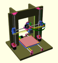
Wiener90
This page is a development stub. Please enhance this page by adding information, cad files, nice big images, and well structured data!
Release status: experimental
| Description | A Mendel90 derivative
|
| License | GPL
|
| Author | |
| Contributors | |
| Based-on | |
| Categories | |
| CAD Models | Awaiting prototype testing
|
| External Link |
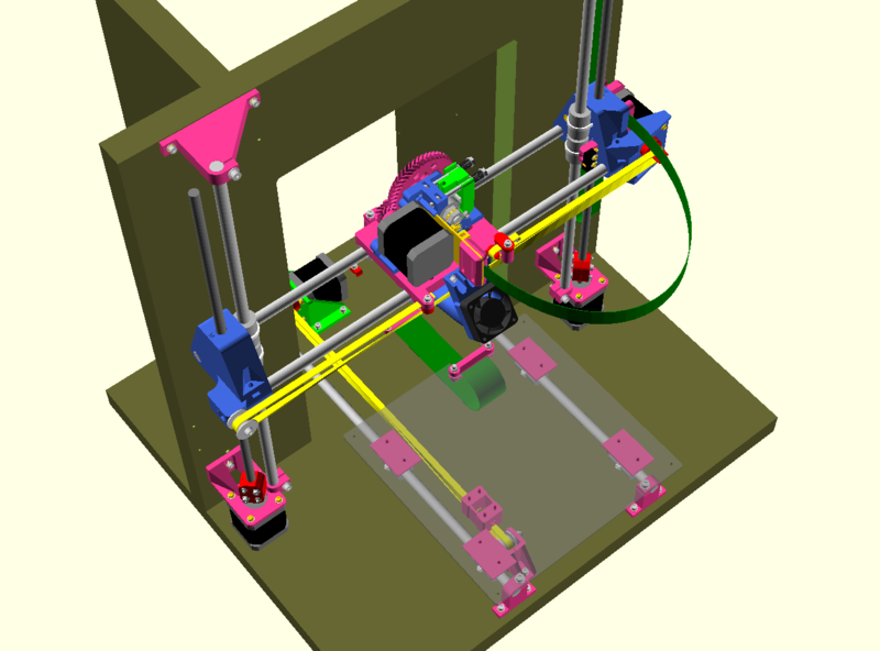
Wiener90, (pronounced "Vee-ner Ninty") is a derivative of Mendel90. The name is a nod to both the city of Vienna, home town of a friend who asked which printer he should build - and quite coincidentally, to a great mathematician and philosopher, Norbert Wiener who among many notable achievements was "an early researcher of stochastic and noise processes".
Shortly after my friend asked me for 3D printer recommendations, he naturally asked me to print parts for the Mendel90 that had been top of my DIY recommendations. Keen as I was to incorporate an existing well tested 'vee-block' design for mounting all the linear bearings into Mendel90, tinkering with OpensSCAD began and so too my love-hate relationship with it. Wiener90 is thus the embodiment of various mods, hacks, design preferences, the odd necessity and a few original ideas into the skelton of Mendel90.
Features
- Frame is 25mm (possibly thinner) MDF material screwed and glued into routed alignment trenches or dados. The thicker material ought to further dampen any audible resonance Mendel90 reportedly produced. Other sheet materials such as use of compact grade laminate (CGL) and furniture industry style assembly methods may be investigated.
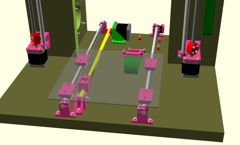
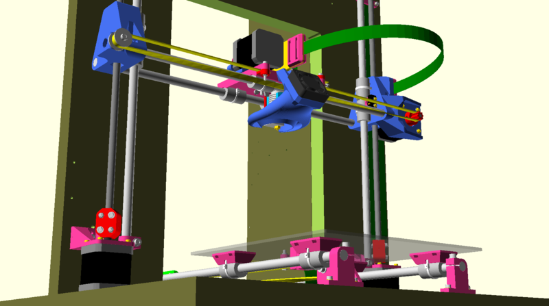
- Vee-block style linear bearing blocks for all axes: For X and Y-axis locations, this feature results in less plastic usage than the more prevalent cup-style linear bearing blocks without sacrificing bearing security or locational accuracy.
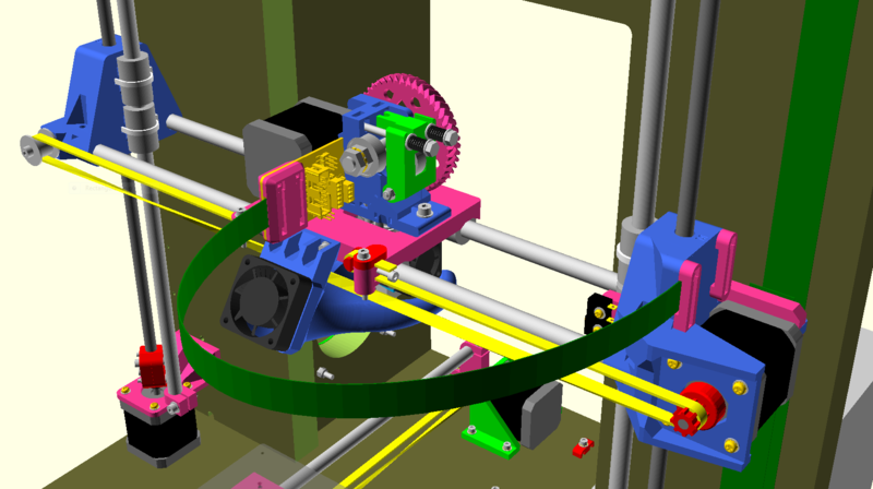
- Incorporating vee-block style mounts for the Z-axis linear bearings required the print orientation of the X Ends to be changed (vs Mendel90) to ensure best accuracy. This should result in greater rigidity of the X Ends (Motor End especially) as they are now significantly more solid than both Mendel90 and Prusa Mendel.
- X-axis rail ends are secured in sockets by a pipe-vice-like method - not too dissimilar to original Prusa Mendel, however due to the change in X End build orientation, the rail mounting points are virtually flex-free.
- X end vitamin count is reduced: Experimental X Motor End ribbon cable clamps replace some vitamins with a combination of clip-features and zipties. Additionally, experimental use of wood screws is used in assembling the X Motor End Endstop and X Motor End Ribbon Cable brackets to X Motor End.
- X carriage is optimised for the E3D hotend, but should work equally well for others. It includes a captive nut solution to the problem of the E3D extruder heatsink fan otherwise preventing use of a wingnut. The distance between X rails remains unchanged, therefore an original Mendel90 carriage and other derivatives ought to fit equally well.
- Combined Y-axis belt clamp and tensioner block. The Y Motor Idler bracket is now fixed in location on the base and Y belt tension is achieved with a mechanism identical to that of the X-axis belt.
- A Mashup of Jonas Kuehling's Greg's Wade reloaded with Nophead's Mendel90 Wade, plus addition of a mounting slot for an alternative (experimental) Extruder PCB.
- Relocation of the Y-axis stepper motor and limit switch to the rear of the base. This both shortens and somewhat simplifies wiring routing.
- Y-axis rail pair is 'reverted' to being of equal length, 'a la Mendel', the rationale being threefold: It may be a little easier/more accurate to measure and set identically the distance between two rails of equal length; especially when the base is not CNC manufactured and bar clamp mounting hole centers not precisely located. Equally, it is possibly a little easier to mark out accurately by hand, the hole centers for the Y bar clamp mounting hardware when they share a common 'Y edge distance' on the base. Also, when getting ground and hardened rails cut to length by a local supplier, ordering "QTY two of 3 rail lengths" is slightly simpler than "QTY two of 2 lengths" + "QTY one each of another 2 lengths". Finally, (irrationally perhaps) I prefer the overall appearance of a more symmetrical configuration.
- All rails each carry two linear bearings. On the X-axis, this turned out to be a necessity in order to incorporate the vee-block linear bearing mount method.
Update
2016-07-09:
- The rear uprights still aren't quite in the right location in the openSCAD model,
- a few frame holes are still in the wrong locations, but otherwise hardware is generally located correctly.
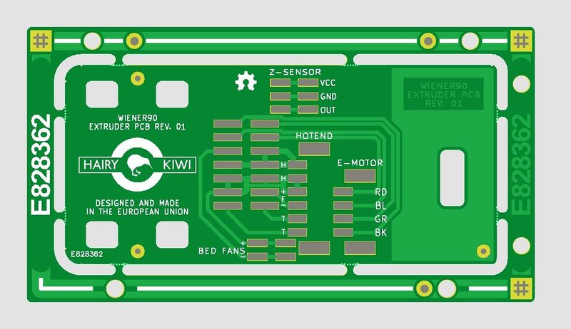
- The prototype extruder PCB design, entirely SMD (below) is out for manufacture. Much as I wanted to fully incorporate power and signal lines for DC42's differential modulated IR height sensor into the extruder PCB design, it would have involved a big redesign of the x-motor-end bracket ribbon cable clips and loss of compatibility with existing Mendel90 extruder ribbon cable wiring, so I went instead for partial integration: the three wires from the IR height PCB can be connected to the Wiener90 extruder PCB and another three-wire lead can either be jury-rigged along the main extruder PCB ribbon cable, or fitted and removed each time bed levelling is performed; not ideal, but progress nonetheless.
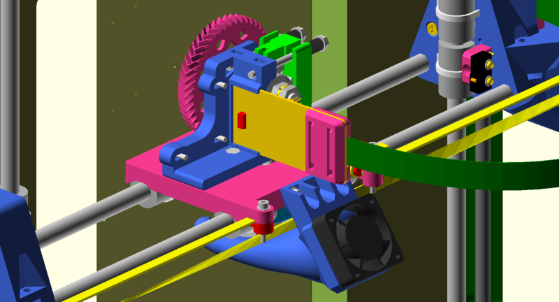
Here's the extruder motor removed to show the method of retaining the PCB in the slot, with the red block acting as a clamp. Not visible: the red block has an M3 nut trap in it, with two 0.4mm perimeters either side:
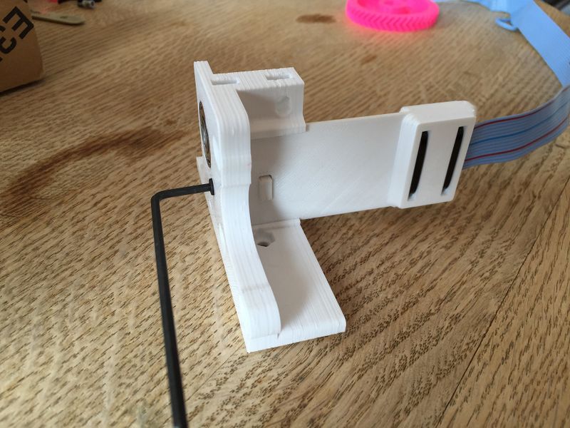
The extruder PCB retention method was tested using a 3D printed dummy-PCB. I'm really happy to report that it stays in place very securely:
More updates to follow in August.
