Reflow Toaster Oven using Thermistor
Release status: working
| Description | reflow solder surface mount printed circuits
|
| License | GPL
|
| Author | |
| Contributors | |
| Based-on | [[]]
|
| Categories | |
| CAD Models | |
| External Link |
See also Toaster_Oven_Reflow_Technique and HotplateReflowTechnique.
Introduction
This page shows hot to use a toaster oven to reflow solder mount printed circuit boards adapted from this technique: Toaster_Oven_Reflow_Technique with two main differences: 1) it uses a thermistor instead of a thermocouple and 2) it waits for the toaster oven to reach the target temperature before incrementing the timer counter.
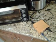
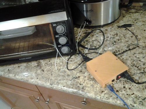
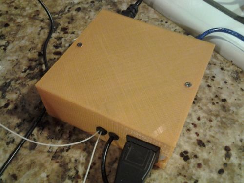
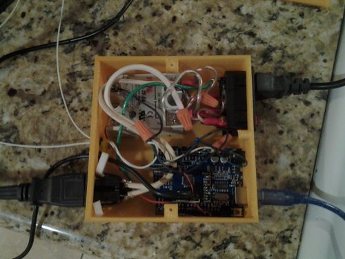
In addition, there is a 3D printable case here [1] that uses a standard Arduino Uno, 120V relay, and power sockets easily found on Ebay ro Aliexpress.
Firmware
Here is the original Arduino control program with the above mentioned adaptations.
/*

  Toaster Oven SMT soldering control

  Adrian Bowyer

  2 November 2011

  Licence: GPL

*/
//2016-08-14 rev02- changed to wait until temperature is reached before incrementing timer - TPH
//2016-02-06 rev01- adapted by Ted Huntington for a thermistor
//with help from: http://iwantmyreal.name/blog/2012/09/23/measuring-the-temperature-with-an-arduino-and-a-thermistor which is Copyright (C) 2012 Sam Davies
#include <math.h>

double ThermistorResistor = 4700;  //resistor used to voltage divide with the resistance of the thermistor
double ThermistorBeta = 3950; //Thermistor Beta
double ThermistorRefTemp = 298.15; //thermistor reference termperature (in Kelvin)
double ThermistorRefResistance = 100000; //Thermistor Reference Resistance 100k ohms

const int heatPin =  13;     // the number of the LED pin.  This also controls the heater
int heatState = LOW;         // heatState used to set the LED and heater
long previousMillis = 0;     // will store last time LED/heater was updated
const long interval = 1000;  // interval at which to sample temperature (milliseconds)
const int tempPin = 0;       // Analogue pin for temperature reading
long time = 0;               // Time since start in seconds
bool done=false;             // Flag to indicate that the process has finished

// The temperature/time profile as {secs, temp}
// This profile is linearly interpolated to get the required temperature at any time.
// PLEN is the number of entries
#define PLEN 6
long profile[PLEN][2] = { {0, 15}, {120, 150}, {220, 183}, {280, 215}, {320, 183}, {350, 0} };

// Linearly interpolate the profile for the current time in secs, t

int target(long t)
{
  if(t <= profile[0][0])
   return profile[0][1];
  if(t >= profile[PLEN-1][0])
  {
   done = true; // We are off the end of the time curve
   return profile[PLEN-1][1];
  }
  for(int i = 1; i < PLEN-1; i++)
  {
     if(t <= profile[i][0])
       return (int)(profile[i-1][1] + ((t - profile[i-1][0])*(profile[i][1] - profile[i-1][1]))/
         (profile[i][0] - profile[i-1][0]));
  }
  return 0;
}

// Measure the actual temperature from the thermister

int temperature()
{
  int ADCValue;
  double ADCVoltage;
  double Temp,TempC,TempF;
  double Resistance;

  //for thermocouple with amplifier:
// return ( 5.0 * analogRead(tempPin) * 100.0) / 1024.0;

//
 ADCValue=analogRead(tempPin);
 ADCVoltage = float(ADCValue) / 1024 * 5;
 Serial.print("ADC: ");
 Serial.print(ADCVoltage);
 Serial.print("V ");
 Resistance= ThermistorResistor / (5 / ADCVoltage - 1);
 Temp = 1.0 / (1.0/ThermistorRefTemp + log(Resistance / ThermistorRefResistance) / ThermistorBeta);
 TempC = Temp - 273.15;            // Convert Kelvin to Celcius
 TempF = (TempC * 9.0)/ 5.0 + 32.0; // Convert Celcius to Fahrenheit
 Serial.print("Temp: ");
 Serial.print(TempF);
 Serial.print("F ");
 Serial.print(TempC);
 Serial.println("C");
 return((int)TempC);
}

// Get the show on the road

void setup() {

  pinMode(heatPin, OUTPUT);
  pinMode(tempPin, INPUT);
  Serial.begin(9600);
  Serial.println("\n\n\nTime\ttarget\ttemp (C)");
  done = false;
}

// Go round and round

void loop()
{
  int t;
  unsigned long currentMillis = millis();

  if(currentMillis - previousMillis > interval)
  {
    previousMillis = currentMillis; // set next time

    // Get the actual temperature

    t = temperature();


    // Find the target temperature

    int tg = target(time);


    //only increment timer if current temperature is >= target temp-
    //otherwise PCB might be underheated- and overheating for a few seconds is not too big a concern+++++++++++++
    if (t >= tg)  //current temp is less than target temp
    {
    // One second has passed
    time++;
    }

    // Simple bang-bang temperature control

    if (t < tg)
    {
      heatState = HIGH;
      Serial.println("on");
    } else
    {
      heatState = LOW;
      Serial.println("off");
    }

    // Turn the heater on or off (and the LED)
    digitalWrite(heatPin, heatState);

    // Keep the user amused
    if(done)
    {
      Serial.print((char)0x07);  // Bell to wake the user up...
      Serial.print((char)0x07);
      Serial.print("FINISHED ");
    }
    Serial.print(time);
    Serial.print("\t");
    Serial.print(tg);
    Serial.print("\t");
    Serial.println(t);
  }
}
Upload the firmware above into the Arduino.
Operation
(adapted from Toaster_Oven_Reflow_Technique) Plug the controller into a mains socket that is, for the moment, switched off.
Plug the oven into the controller.
Connect the Arduino to a computer via a USB cable. You can use the terminal emulator in the Arduino development environment to monitor what is going on, or you can use stand-alone programs like Miniterm (Linux) and Hyperterminal (Windows).
Tape the thermistor inside the oven or to a part of the PCB where it won't interfere with the components using Kapton tape.
Place the PCB on the shelf in the middle of the oven.
Close the oven door on the thermistor lead, taking care that there is slack so the PCB doesn't move when you do this.
Once the Arduino is connected to a computer via USB, the code should start running.


