RAMPSSB
|
English • العربية • български • català • čeština • Deutsch • Ελληνικά • español • فارسی • français • hrvatski • magyar • italiano • română • 日本語 • 한국어 • lietuvių • Nederlands • norsk • polski • português • русский • Türkçe • українська • 中文(中国大陆) • 中文(台灣) • עברית • azərbaycanca • |
This page is a development stub. Please enhance this page by adding information, cad files, nice big images, and well structured data!
Release status: Working
| Description | RAMPS Servo Board
|
| License | |
| Author | |
| Contributors | |
| Based-on | |
| Categories | |
| CAD Models | |
| External Link |
Contents
- 1 Summary
- 2 Reverse Polarity Warning
- 3 Overview Video
- 4 Schematic
- 5 Layout
- 6 Open Source Files
- 7 Where to get it?
- 8 Firmware Information
- 9 Pin Definitions for the Micro
- 10 Bill of Materials
- 11 Assembly
- 11.1 Step 1: Gathering components
- 11.2 Step 2: basic pin headers
- 11.3 Step 3: main power rails
- 11.4 Step 4: PWM LEDs
- 11.5 Step 5: The Arduino Pro Micros
- 11.6 Step 6: TX/RX/Vmot pins
- 11.7 Step 7: Connecting to RAMPS
- 11.8 Step 9: Adding a fan (Optional)
- 11.9 Step 10: Wiring
- 11.10 Step 11: Adding a second DC motor driver (Optional)
- 11.11 Step 12: Wiring the Endstops
- 11.12 Step 13: Uploading the Firmware
- 11.13 Step 14: Covering the power traces (optional)
- 11.14 Step 15: Attach motors and encoder
- 11.15 Step 16: Apply power
Summary
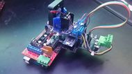
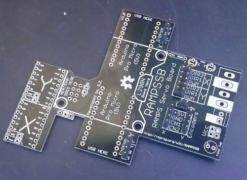
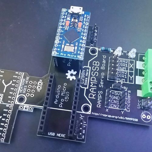
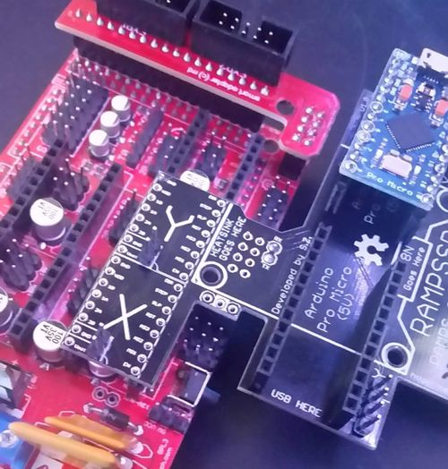
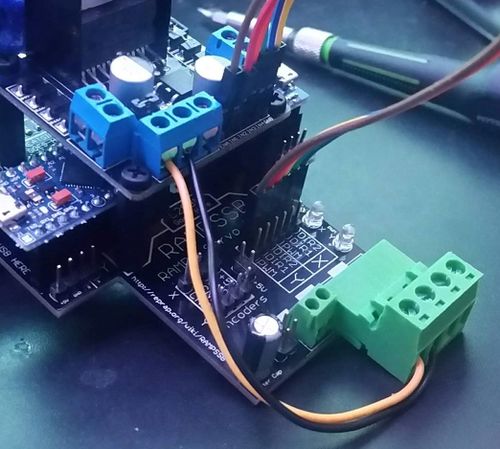
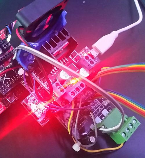
RAMPSSB (RAMPS Servo Board) is a shield that attaches to the AUX1 pins of the common 3D printer control board, RAMPS.
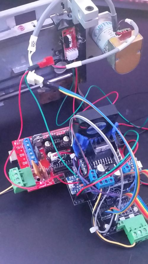
It converts the X and Y stepper motor driver carriers into quadrature encoder closed loop control DC motor drivers. This means that if the carriage gets knocked out of place, it will bring itself back to the same location. No more skipped layers! It also allows RAMPS boards to control things like inkjet printer motion carriages, using any 0-24V quadrature encoder motor that has a optical, hall effect, or mechanical rotary encoder.
Does not interfere with the Reprap.me Stepper Expander or RepRapDiscount's RepRapDiscount Smart Controller. With modification (removing the TX, RX, and AUX1 headers, and using longer stepper carriage pins), it's even compatible with my other board, the RAMPSXB. The first 3 sets of servo pins are untouched, and the other is merely used as a mechanical standoff, so it can be flipped and used as well if necessary. AUX1 is nothing but a mechanical standoff, but the TX and RX pins of the arduino mega are broken out, and can be accessed on the bottom of the board. Technically it is compatible with 24V, but make sure your drivers can handle it before testing on a live system.
No RAMPS? This system can be used as a standalone Step/Direction to Closed Loop DC motor converter by wiring GND, Vdd (+5V), step, direction, and enable on the driver carriage of the RAMPSSB to whatever your control board is, provided that it uses Pololu stepper carriages.
There is a second set of pins for all the logic pins, which can be used to attach a second driver board, run in parallel for more power, or for logic analyzer leads. If you intend to add a second Driver, you can stack it on top of the first by using another set of standoffs (which are available as a cheap assortment from Harbor Freight or Microcenter).
Reverse Polarity Warning
Overview Video
<videoflash type="youtube">hFBo3W_ZEq8</videoflash>
Schematic
Layout
Open Source Files
EAGLE, gerber, CAD, and Firmware files can be found here: https://github.com/SZiv/RAMPSSB
Where to get it?
No manufacturers for this yet. ¯\_(ツ)_/¯ The individual parts are easy to find, and everything is through-hole, so its not too hard to make if you have terminals and pin header lying around. The only discrete components are 2 3mm LEDs, a 200ohm resistor for them, and a filter capacitor, but even those are technically optional.
Firmware Information
The firmware could use some work. While it does work, it is a bit shakey, and while the hardware is stable, the software cannot be trusted with high precision movements at this time. Anyone with control theory expereience is encouraged to work on improving the firmware and if you can make it work better, let me know and I can add it to the official github.
Firmware is uploaded to the Pro Micros individually, and the configuration variables at the beginning should be adapted to your hardware. Since each axis, X and Y, may use different hardware for control, the firmware for each Pro micro may be different, so you should save the firmware twice and label it for each axis. The pinouts are the same, so that shouldn't change, but the configuration variables may be different. Once you add the PID, GPIO, and Encoder libraries (included in the Repo) to your sketchbook folder for Arduino and open the firmware up, you will see a set of these configuration variables.
- If you’ve worked with CNC machines before, you are probably familiar with the concept of “steps per mm”; it’s a value of how many steps on a stepper motor it takes to move whatever fixture you use as a carriage 1mm. This system take that info from your RAMPS firmware, and calculates a “target” position by using (steps per mm x number of steps), adding or removing steps from its count based off of how many steps it receives on the step pin. If you are having issues with missed steps on the RAMPSSB, try reducing the steps per mm value on the RAMPS and RAMPSSB.
- To convert this to an actual usable value for an “actual” DC motor encoder value, there should be a “encoder ticks per mm” value, but since finding that is hard, that variable has been separated into “Encoder ticks per revolution” (cpr), which should be listed on your motor datasheet, and “mm per revolution” (mmpr), which is found by simply marking your carriage, rotating the encoder shaft 5 complete revolutions, measuring the distance and dividing by 5. Encoder Ticks per revolution is then divided by mm per revolution inside the firmware to get the encoder ticks per mm.
Other than that:
- Acceptable error is the amount of error you are willing to accept in the final product. This is typically on the order of a few dozen microns, but the smaller it is the more prone to jitter the system is, although PID tuning can help correct this.
- Minimum PWM is the minimum PWM value that the motor requires in order to spin as slow as it can. This is to prevent jerk from rampup on the PID value, so it starts at this value, so it can smoothly increase and decrease in speed.
- Maximum PWM is the maximum PWM the motor can receive while not making the Arduino freeze. This is uncommon on small motors with quadrature encoders of 300 counts or less, but on some high precision, 24V, 2000 count per revolution motors, running them at full speed with cause the Arduino to never get free of the interrupt vector, and thus freeze up until the motor stops.
- Endstopinverted is just as it sounds; if you are using a normally open switch, such as mechanical endstops, leave as false. If you are using NC endstops, such as optical endstops, make true.
- Diagnostic will print to the serial monitor the target, actual, and inputs and outputs for the PID. turn this off after you have finished calibrating.
- Kp, Ki, and Kd are the inputs for the PID controller for the motor. This is very difficult to explain, and may take some trial and error, but your best bet would be to start at 0 for all of them, and slowly raise Kp until the carriage oscillates, then crank up Kd until it stops. Look on the diagnostic for the “Input”. That’s the input to the PID, and the error between the target and the actual. The closer this number is to 0, with as little overshoot as possible, the better. Once the Kp and Kd values are set, you should have a smooth movement, but it may be stuck with a steady state error it will not attempt to correct. If you get this, you can sort of correct it by adding some Ki, but since the error will never be positive, then the PWM will creep up over time, and never reduce, so it's not suggested to add Ki unless you know what you're doing.
Pin Definitions for the Micro
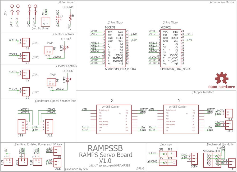
Direction Input - 1
Step Input - 0
Enable Input - 4
Output Direction 1 - 8
Output Direction 2 - 9
Output PWM - 5
Encoder Input 1 - 2
Encoder Input 2 - 3
Endstop Input - 7
Bill of Materials
| Description | Quantity | Package | Notes |
|---|---|---|---|
| resistor, 200 ohms | 1 | 7mm | LED current limiting resistor |
| LED | 2 | 3mm | LEDs for visualizing PWM outputs |
| L298N DC Motor Driver | 1 | N/A | DC Motor Driver. There are two different versions of these, make sure you get the square version with the screw terminals! |
| 40mm fan | 1 | 40mm | Cooling fan for DC motor driver |
| 20mm M3 Spacers | 3 | N/A | M3 Standoffs for the DC motor driver |
| Misc M3 screws | 5 | N/A | for securing the standoffs to the driver and the fan to the printed bracket. |
| Arduino Pro Micro | 2 | N/A | Developed by Sparkfun, but there are a lot of cheap clones. Necessary because of all of its interrupt pins. |
| Screw Terminals | 1 | 3.5mm | Spare output power terminal. Not strictly necessary. |
| Screw Terminals | 2 | 5mm | Input/output power terminals. |
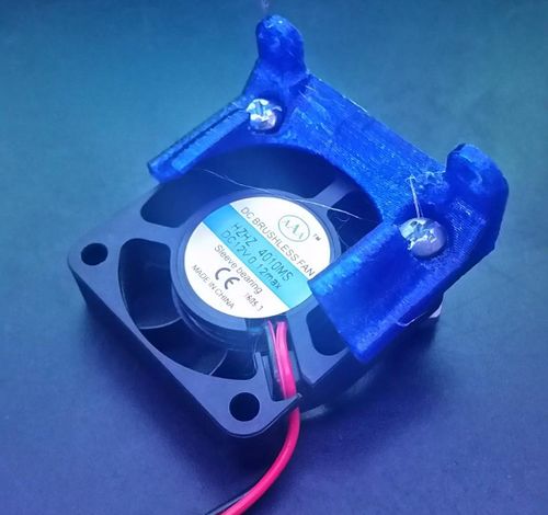
| 3D printed fan bracket | 1 | N/A | Fan duct for the 40mm fan that connects it to the driver. You can find the STL and STEP in the Github Repo. |
| Male/Female Pin Headers | A lot? ¯\_(ツ)_/¯ | 0.1" spacing. | Buy a couple of Female double rows, male double rows, male single rows, and female single rows. |
| Female-female jumper wires | 20 | 0.1" spacing. | Jumper wires for connecting the DC motor drivers and endstop wires. |
| PCB | 1 | N/A | The Actual PCB. SEEEDstudio sells them for cheap. |
Assembly
Step 1: Gathering components
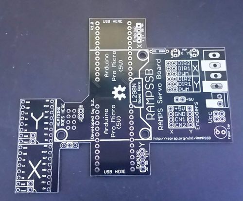
Gather all components listed on the BOM above. You will also need a soldering iron and solder, but that’s about it for tools. This will take maybe 20-30 minutes of assembly time. Begin with the blank PCB.
Step 2: basic pin headers
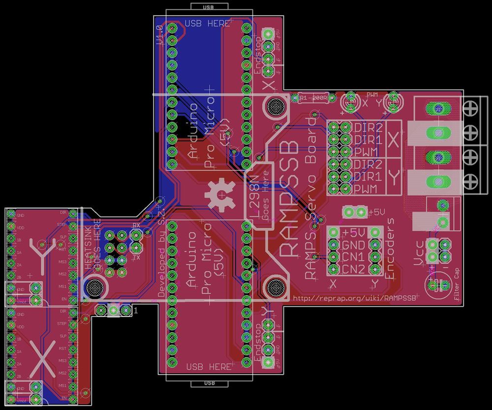
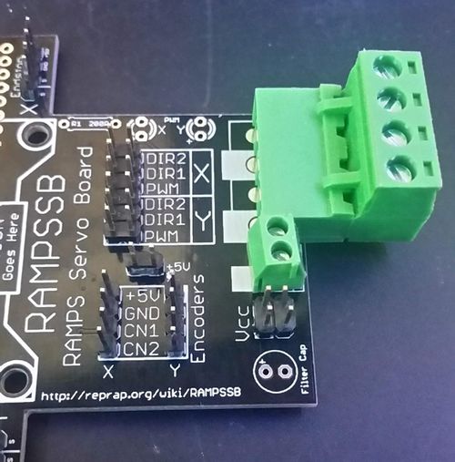
Attach the X and Y data pin headers (2x6) , as well as the two encoder pins (1x4), the 5V rail (1x2) and two endstop pin headers (1x4), and solder them in place
Step 3: main power rails
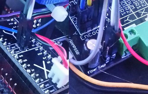
These connectors are separate from the rest of the circuit, and serve only to act as a power distribution board for the motor drivers. Solder on the 2 sets of 5mm pitch terminal connectors (I like the ones from the RAMPs board, but standard screw terminals work too). If your system requires it, there is also a VCC pinout (which takes a 2x2 pin headers), and give you two connectors for fans or other systems, if your servo power is different than your RAMPS power. If you feel that a capacitor is nessissary to filter the output of your power supply, you can attach one at the “filter cap” location.
Step 4: PWM LEDs
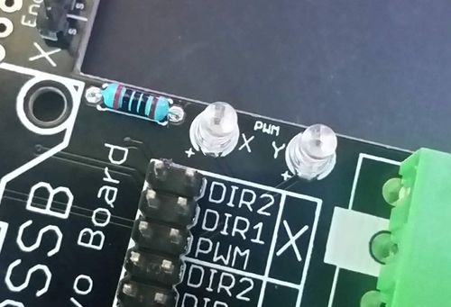
Here we go, the only passives in the whole build! Solder two 3mm LEDs to the X and Y locations, and a 200 ohm 7mm current limiting resistor to the board. These lights flash when the motors are being told to move, and can help with debugging.
Step 5: The Arduino Pro Micros
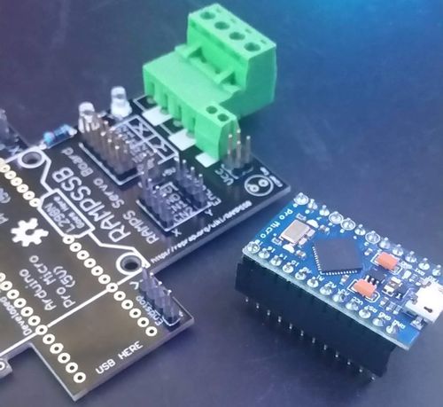
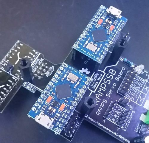
Cut two 1x12 pieces of female pin header, and attach them to the pins on the bottom of a pro micro. Once that is done, put them into the PCB with the USB side facing the “USB HERE” tag, tack the corners down, and solder the pins.
Aaaand repeat on the other side. Remember that the USB is on the opposite side as the first one!
Step 6: TX/RX/Vmot pins
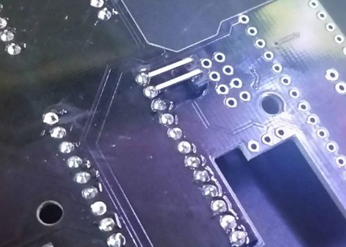
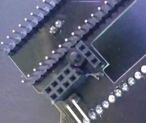
This is optional, but it breaks out the TX and RX pins of the Arduino Mega. On the RAMPS board. If you intend to use a HC-05 chip or something that requires serial, it is highly recommended that you add these. I used right angle connectors, but you can use straight if you want. Flip the board over and break out these two pins on the back side with a single 1x2 header.
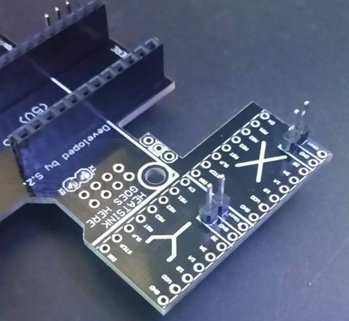
Before we put the whole thing together, attach these two headers to the top of the PCB. These are GND and Vmot pins out of the RAMPS board, and they give you access to the voltage off the RAMPS board. If you are, for example, running 24V DC motors, but want to use a 12V fan, this gives you that connector.
Step 7: Connecting to RAMPS
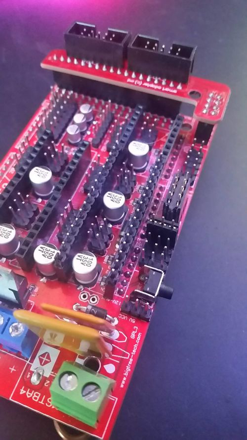
Cut two pieces of 1x16 male header and put them into the sockets for the X and Y stepper drivers, a 1x3 piece of female header and put it into the 4th servo connector, as well a 2x4 piece of female header, and put it into AUX 1. Make sure this 2x4 is sanded or cut down as small as it can be. Also, remove and save the jumpers from the microstepping jumpers, as this system does not use them.
It may take some wiggling and bending of the pins on the RAMPS, but you should be able to work the pins into the sockets and solder them on.
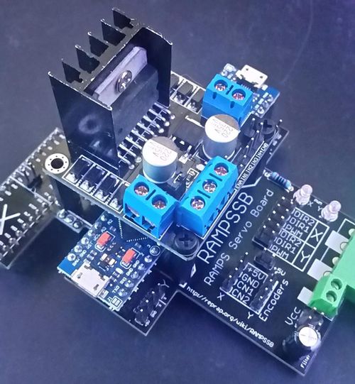
‘‘‘Step 8: Attaching the DC driver’‘‘ Start by attaching both of the Pro Micros. You won’t able to reach them easily after this, so make sure they are nice and tight. After that attach 3 20mm M3 nylon spacers (4 dollars for an assortment at Harbor Freight or Microcenter) into the holes on the PCB, so that they are a good 5mm above the top of the Pro Micros.
It may take some wiggling and bending of the pins on the RAMPS, but you should be able to work the pins into the sockets and solder them on. Remember what I said about the 2x4 being really small? That’s because this nut is really hard to get into place, but with some razor blade antics and tweezers, it doesn’t take too long. Be sure not to cut the PCB though!
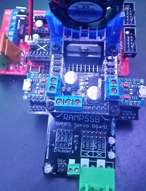
Alright almost done, put the L298N DC motor driver on top of the spacers, and screw down two M3 screws into the two spacers nearest the terminal blocks.
If you plan on using a fairly low power motor, such as the ones inside of inkjet printers, you can skip the next step and screw down that last spacer. However, if you plan on using something that consumes more than about 1A continuous or 4A peak, it is suggested to add a fan.
Step 9: Adding a fan (Optional)
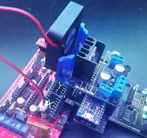
3D print the model “RAMPSSBSingleFanMount.stl” found inside the github repo. Once it’s finished, attach a 40mm fan and secure it with screws (I used 6-32s, but M3s should work as well).
Screw the assembly into the final spacer, and attach another M3 screw and nut to hold the other side of the assembly in place. If you are using the same voltage of fan as your RAMPS board’s stepper motor supply, you can plug the fan into the broken out Vmot pins.
Step 10: Wiring
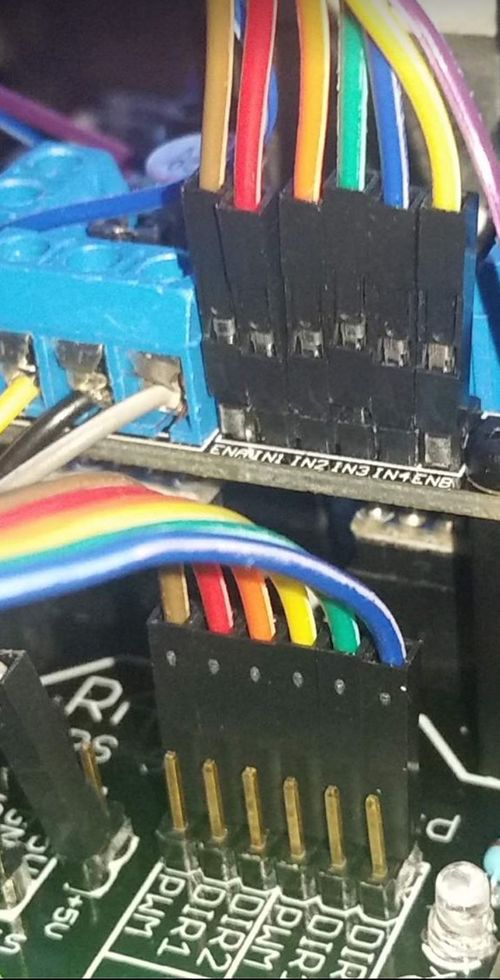
If you look at the top of the DC motor driver, you should see pins ENA, IN1, IN2, IN3, IN4, ENB. Remove the jumper on ENA and ENB. Below that, the RAMPSSB has YDIR1, YDIR2, YPWM, YDIR1, YDIR2, YPWM.
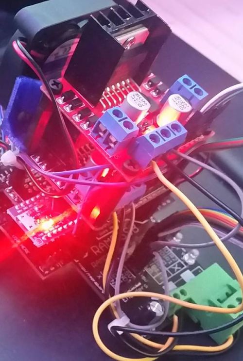
Using female-female jumper wire, connect these pins so that: XPWM - > ENA XDIR1 -> IN1 XDIR2 -> IN2 YPWM - > ENB YDIR1 -> IN3 YDIR2 -> IN4
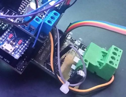
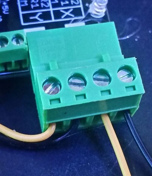
Now, wire the power rail on the DC motor driver (yellow) to the white colored connectors on the terminal block, and the GND (black), to the uncolored connectors.
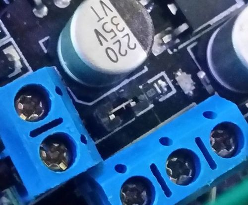
The jumper on top of the DC motor driver…
…is a regulator that provides a 5V output if and only if 12V is applied. While the driver IC is good for up to 30ish volts, and should be able to control 24V just fine, this output is not rated for it. IF YOU ARE USING >12V, disconnect the jumper on top of the DC motor driver and DO NOT connect the third terminal connector. If you are using 12V or less, keep this jumper in place, and cut a female jumper in half, and connect the third terminal block socket to the +5V rail on the PCB. This can actually give you more power than the Arduino can provide, and may be useful for servos and the like.
Step 11: Adding a second DC motor driver (Optional)
Again, this step is not necessary unless you intend to run motors that use more than 2A continuous current. You will notice that there are two sets of all the digital pins coming out of the RAMPSSB. This is for two reasons; debugging with a logic analyzer, and to provide a second DC motor driver output. Each DC motor driver supports two channels, but each channel has a maximum continuous current of 2A. If you need to run a 3.5A motor and a 1.5A motor, you need a total of three channels, with two running in parallel. Because these L298N boards are pretty standardized, we can just tack another DC motor driver on top of the first with another set of spacers, use the spare power header, and the other +5V rail, then connect a second set of female jumpers in parallel with the first, that connect XPWM - > ENA XDIR1 -> IN1 XDIR2 -> IN2 YPWM - > ENB YDIR1 -> IN3 YDIR2 -> IN4
On the second motor driver, and connect the output rails on both channels of both motor drivers together. At this point, it looks a little ridiculous, but it does work, and this gives 4A continuous current for both the X and Y axis.
Step 12: Wiring the Endstops
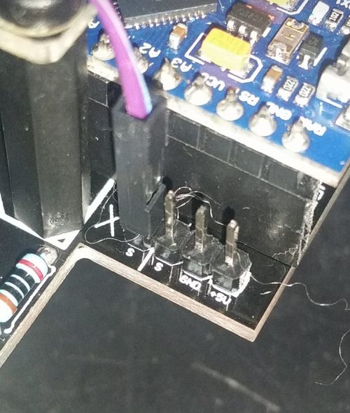
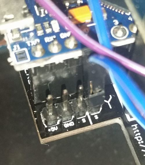
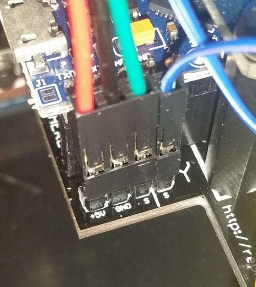
Since both the RAMPS and RAMPSSB need to know when an endstop has been triggered at the same time, the RAMPSSB uses a man-in-the-middle method. There is a strip of 4 pins, which are +5V, GND, Signal, and Signal. The two signals are tied together, and the +5V, GND, Signal setup is the same as the RAMPS.
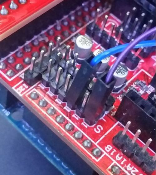
Using another two female jumper wires, connect the second servo pins of both the X and Y axes to the X and Y signal pins on the RAMPS board.
Now, when you plug the X and Y endstops into the RAMPSSB, both the RAMPS and the RAMPSSB will be able to read the signals. Just remember that the RAMPSSB connectors are mirrors of each other, so double check the directionality.
Step 13: Uploading the Firmware
Well the hardware is done, onto the firmware. Read the "Firmware Information" section for more info. Once all the variables are set, and the libraries are added to your sketchbook, save the sketch, and upload it to the Pro Micro. Repeat for the other axis, and you should be good to go.
Step 14: Covering the power traces (optional)
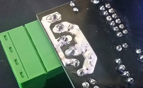
This should theoretically never be necessary because the traces on their own can handle 8A, and even two DC motor drivers can only take 8A total, but if for some reason you have something that requires more power out of the distribution side of the board, you can cover these traces with solder to increase their current capacity to 12A.
Step 15: Attach motors and encoder
Attach the motor’s power rails to the DC motor driver outputs, and attach the encoder pins so that +5V -> +5V GND -> GND CN1 -> channel 1 of quadrature encoder or the only encoder of a single encoder motor CN2 -> channel 2 of quadrature encoder
Single encoder motors (i.e. not quadrature encoders) are currently not supported, but there are plans to do so in the future.
Step 16: Apply power
Attach the positive power from your power supply to the white connector on the terminal block. And the ground from the power supply to the unmarked connector.
Or, if you are using a small motor that uses the same voltage as your RAMPS board (<0.5A continuous draw), you can connect two jumpers from the VCC header near the filter capacitor to the Vmot pin and power the motors off the RAMPS power supply instead.
