Prusa Mendel Assembly/ru
|
English • العربية • български • català • čeština • Deutsch • Ελληνικά • español • فارسی • français • hrvatski • magyar • italiano • română • 日本語 • 한국어 • lietuvių • Nederlands • norsk • polski • português • русский • Türkçe • українська • 中文(中国大陆) • 中文(台灣) • עברית • azərbaycanca • |
Прим: статья находится на стадии перевода. Перевод начат 2.12.12
Contents
- 1 Подготовка
- 2 Инструкция сборки
- 2.1 Треугольные рамы
- 2.2 Передний резьбовой прут
- 2.3 Задние резьбовые пруты
- 2.4 Верхние резьбовые пруты
- 2.5 Затягивание рамы
- 2.6 Сборка оси Y
- 2.7 Assembling the X-axis
- 2.8 Assembling the Z-axis
- 2.9 Installing the X Carriage
- 2.10 Attaching the Print Bed
- 2.11 Wiring the electronics
- 2.12 Firmware Calibration
Подготовка
Перед началом сборки Prusa Mendel, убедитесь, что у вас есть все необохдимые детали. Список деталей доступен по ссылке Prusa Mendel.
Если вы собираете Iteration 2, обратите внимание на Prusa_Mendel_Assembly_(iteration_2) так как части и последовательность сборки немного упрощены без использования клея.
Для того чтобы визуально ориентироваться, можете взглянуть на галерею со съемкой сборки Prusa Mendel.
Замечания:
- Heating the flat side of a bushing with a hair dryer or heat gun before snapping onto the smooth bar can keep it from snapping.
- If you're using serrated washers these should only be used between nut and plastic - nut-to-fender and fender-to-bearing washers should be flat.
- Возможно вам так же захочется взглянуть на заметки Adrian's Prusa Notes, где так же показан вариант сборки Prusa Mendel.
- Большинство шагов сборки совершенно безопасны (для здоровья), если они выполняются правильно. Инструкция по безопасности доступна здесь: Health and Safety.
- Существует несколько вариантов сборки Prusa Mendel и скорее всего к каждому можно найти инструкцию на этом сайте. Пожалуйста постарайтесь найти свой вариант сборки перед тем как править существующие инструкции.
Инструкция сборки
Треугольные рамы
Примерное время сборки: 15 мин. на каждый треугольник, всего где-то 30 мин.
С боковых сторон Прусы есть треугольные рамы. Вам нужно будет сделать две, и затем соединить их вместе (соединение описывается в следующем разделе) для того чтобы сформировать каркас принтера. Левая и правая боковины представляют собой равнобедренный треугольник с фиксирующими пластиковыми деталями в его вершинах. Для сборки вы можете использовать детали с ножками и без (с ножками смотрятся лучше, но это не критично). В инструкции используются с ножками.
Необходимые детали(на каждый треугольник)
- 2 пластиковых детали с ножками

- 1 пластиковая деталь - вершина(без ножки)

- 1 пластиковый стяжной зажим.

- 3 прута с резьбой 370мм M8.
- 14 гаек M8.
- 14 шайб M8.
- (Не обязательно, но рекомендуется) Кусок резьбового прута или дерева или любого другого материала 290мм длинной. Это ваш мерный шаблон J1.
<videoflash>-PFy4KhW9gE</videoflash>
- Возьмите один прут с резбой 370мм, и наденьте на него шайбу M8 в середину.
- Возьмите пластиковый стяжной зажим (в форме английской буквы U, с двумя отверстиями вверху) и наденьте его через отверстия на прут. Протяните его до шайбы, к середине прута.
- Наденьте еще одну шайбу с противоположной стороны прута.
- Накрутите две гайки M8 с каждой стороны стяжки до середины, но пока не затягивайте.
- Накрутите еще две гайки с обоих сторон прута, а за ними еще две шайбы. На картинке показано, как это должно в итоге выглядеть. <flickr>5188262096|thumb|right|m|The bar clamp on the threaded rod.</flickr>
- Насадите на прут по бокам две крепежных детали с ножками. Убедитесь, что ножки ориентированы в одном направлении, а выступы на деталях напротив ножек смотрят в разные стороны.
- Измерьте расстояние. Между двумя вершинами оно должно составлять 290мм. Пока можно выставить расстояние приблизительно, но сделайте это прямо сейчас. Если у вас есть мерный шаблон, разместите его между двумя пластиковыми деталями и раздвиньте гайки так, чтобы они точно подходили к пластиковым деталям.
- С внешних сторон прута наденьте по еще одной шайбе и гайке, и затяните их к пластиковым деталям с внешней стороны. Затяните, но не слишком сильно. Нам все еще нужна небольшая степень свободы в этом соединении.
- Возьмите следующий прут с резьбой 370мм M8 и накрутите на него сначала гайку, потом шайбу с каждой стороны. По 5 см от края вполне пойдет.
- Вставьте этот прут в одну из деталей-вершин с ножкой. Этот прут должен оказаться в одной плоскости с предыдущим. Зафиксируйте его с помощью еще одной шайбы и гайки. У вас должно получиться две стороны равнобедренного треугольника.
- Возьмите третий прут и наденьте по шайбе и гайке на каждую сторону. Вставьте его в противоположную ножку и зафиксируйте с помощью гайки и шайбы. У вас должен получится треугольник из прутов с двумя деталями с ножками в обоих углах снизу и пусто на месте третьей вершины.
- Возьмите третью вершину (без ножки) и наденьте ее на пустой угол. Делайте это осторожно, чтобы не лопнул пластик. Возможно придется слегка выкрутить один из прутов. Выверьте длины всех трех сторон и убедитесь, что они равны 290мм. Используйте шаблон, если есть. накрутите по гайке и шайбе на все оставшиеся свободные концы прутов. И затяните их. <flickr>5188259098|thumb|right|m|Готовый треугольник</flickr>
- У вас должен получиться жесткий равносторонний треугольник, с двумя ножками внизу и на пруте между ножками должен быть пластиковый зажим. Слегка затяните гайки вокруг хомута так чтобы он оказался примерно посередине. Не затягивайте слишком сильно. Он может лопнуть. На фото изображено то, что должно в итоге получиться.
- Готово. У вас собран один треугольник. Повторите все процедуры для второго. Треугольники совершенно идентичны.
Для того чтобы убедиться что соответствующие отверстия совпадают на обоих треугольниках, приложите их друг к другу и вставьте в каждое отверстие болт на М8. Болты должны проскальзывать без больших усилий. Подправьте треугольники немного, если где-либо есть несовпадение.
Далее мы соединим два треугольника чтобы сформировать раму Prusa RepRap. Самый простой способ соединения состоит в том, что нужно с начала собрать полностью все что будет на передних и задних прутах и в первую очередь присоединить их к треугольной раме. И затем присоединить пруты с верху треугольников. Именно в такой последовательности все описано в этой инструкции.
Передний резьбовой прут
Примерное время сборки: 30 мин.
Эти два резьбовых прута используются для соединения передней/нижней вершины двух треугольников, а так же для присоедиения к раме Y-направляющих стола и держателя шагового мотора для Y-оси.
Необходимые детали
- 2 собранных рамы-треуголькника
- 2 пластиковых стяжных зажима
- 1 пластиковое крепление для Y-мотора

- 18 гаек M8 (или 16 в определенных модификациях)
- 19 шайб M8 (или 17 в определенных модификациях)
- 2 защитные/фиксирующие шайбы M8x30 (большие)
- 1 608 подшипник
- 2 резьбовых прута 294мм
Инструкция <videoflash>9ut45Pe9gkw</videoflash>
- Сначала соберем нижний прут этой части. Накрутите M8 гайку примерно на середину прута и наденьте за ней шайбу M8.
- Проденьте прут через нижнее отверстие пластикового крепления для Y-мотора (далее в этой части - просто крепление мотора). Нижнее отверстие находится на более длинной прямой части этой детали. <flickr>5373622677|thumb|right|m|Эта длинная прямая часть крепления мотора будет параллельна земле, когда вы закончите.</flickr>
- Наденьте еще одну шайбу и гайку М8 с другой стороны крепления мотора для фиксации.
- Накрутите на каждую сторону прута сначала гайку М8, затем шайбу М8.
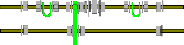
- Теперь соберем верхний прут. Это довольно сложный процесс, так что в конце убедитесь, что вы все собрали правильно. С лева на право, на пруте должны быть: 1 шайба, 2 гайки, 1 шайба, 1 пластиковый стяжной зажим (продетый через дырки), 1 шайба, 2 гайки, 1 шайба, крепление для Y-мотора (длинная часть, которая должна быть в итоге параллельна земле, должна быть направлена от вас), [1 шайба, 1 гайка, 2 шайбы,] 1 защитная/фиксирующая шайба M8x30, 1 шайба, 1 608 подшипник, 1 шайба, 1 защитная/фиксирующая шайба M8x30, 2 гайки, 1 шайба, 1 пластиковый стяжной зажим (снова продетый через дырки), 1 шайба, 2 гайки, 1 шайба.
- Когда вы держите эту часть, деталь для Y-мотора должна быть ориентирована креплениями мотора в вашу сторону. Лучше сверьтесь с картинкой внизу прямо сейчас.ЗАМЕЧАНИЕ: На этой схеме и в тексте далее указано, что используется три шайбы и гайка на верхнем пруте сразу справа от фиксатора мотора. Это несоответствует сборке, представленной внизу в разделеСборка Y-оси, где они пропущенны и защитная шайба сразу примыкает к креплению. Фото были сделаны на уже собранных принтерах в разных вариантах сборок. Это значит что вы должны выбрать в данный момент необходимый вам вариант сборки в зависимости от длинны оси вашего мотора. Если ось длинная - можете добавить эти 3 шайбы и 1 гайку. В противном случае может сложиться ситуация, что длина вашей оси недостаточна для того чтобы шаговый ремень мог двигаться и по шестерне мотора и по подшипнику.
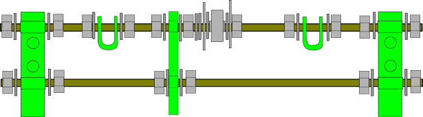
- Теперь вы можете присоединить эту часть к боковым треугольникам. Убедитесь, что длинная часть крепления мотора смотрит в противоположном направлении ОТ треугольников. Проденьте концы прутов через две детали с ножкой. Наденьте шайбу и гайку с каждой стороны для фиксации. Должно получиться так:


Если вы используете широкий ремень (шаговый) на вашей Y оси, смотрите здесь Prusa Mendel Wide Belts.
Задние резьбовые пруты
Примерное время сборки: 20 мин.
Эти два резьбовых прута используются чтобы соединить заднюю нижнюю вершину обоих треугольников а так же для крепления Y-направляющих и фиксатора ремня.
Необходимые детали
- 2 собранные треугольные рамы
- 2 пластиковых стяжных зажима
- 14 M8 гаек
- 14 M8 шайб
- 2 M8x30 защитные/фиксирующие шайбы (большие)
- 1 608 подшипник
- 2 294mm резьбовой прут
Инструкция <videoflash>LfjWQKbxPGI</videoflash> <videoflash>Pern6akmEn4</videoflash>
- Соберем сначала нижний прут. Просто добавьте гайку и шайбу к каждому концу прута.
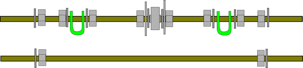
- Теперь соберем верхний. Это еще один достаточно сложный прут, так что убедитесь, что вы все собрали в правильной последовательности. С лева на право на пруте должны быть: 1 шайба, 2 гайки, 1 шайба, 1 стяжной зажим (прут продевается через дырки), 1 шайба, 2 гайки, 1 защитная/фиксирующая шайба, 1 шайба, 1 608 подшипник, 1 шайба,1 защитная/фиксирующая шайба, 2 гайки, 1 шайба, 1 стяжной зажим (прут продет через дырки), 1 шайба, 2 гайки, 1 шайба.
- Оно должно выглядеть как на изображении внизу. Проверьте это сейчас.
- Присоедините два прута к двум оставшимся ножкам на треугольных рамах. Зафиксируйте каждый прут с обоих сторон с помощью шайбы и гайки. Должно получиться как здесь:


Ваша рама уже должна сама стоять на своих ножках без поддержки, но верхние вершины треугольников все еще болтаются. Этим мы и займемся на следующем этапе.
Верхние резьбовые пруты
Примерное время сборки: 10 минут.
Эти два резьбовых прута используются чтобы соединить верхние вершины треугольников, а так же для сборки креплений для Z-моторов.
Необходимые детали
- 2 Собранных и соединенных треугольных рамы.
- 2 Пластиковых фиксатора для Z-мотора

- 12 M8 гаек
- 16 M8 шайб
- 2 440mm резьбовых прута
Инстукции <videoflash>HI77eGBl4gU</videoflash>
- Проденьте один из резьбовых прутов через одну из верхних креплений треугольных рам. Наденьте шайбу, две гайки и еще одну шайбу на ту часть прута, которая будет находиться между вершинами. Вот так это должно выглядеть с верху:

- Сделайте то же самое со вторым прутом. Должно получиться так:

- Проденьте пруты через противоположную вершину второго треугольника. Прокрутите каждую гайку к своей вершине треугольника.
- На каждый из четырех концов прутов добавьте шайбу, гайку и еще одну шайбу. Установка должна выглядеть так:

- Возьмите один из пластиковых креплений для Z-моторов и наденьте его с одной стороны на пруты. Деталь должна смотреть квадратным вырезом вверх, потому что моторы будут закреплены в ней и должны находиться сверху. Добавьте по шайбе и гайке на каждый прут для закрепления детали.
- Сделайте то же самое для противоположной стороны. Верх конструкции теперь должен выглядеть так:


Затягивание рамы
Примерное время сборки: 10 мин.
Теперь, когда рама полностью собрана, мы можем выровнять и затянуть все гайки на каждом пруте. Сейчас вам понадобится ваш мерный шаблон, если он у вас есть или любой другой достаточно точный измерительный инструмент.
Необходимые детали
- 2 пластиковых стяжных зажима
- 4 M8 гайки
- 4 M8 шайбы
- 1 440мм резьбовой прут
- (Не обязательно, но рекомендуется) Кусок резьбового прута или дерева или любого другого материала с длинной примерно 290мм. Это ваш мерный шаблон J1.
- (Не обязательно, но рекомендуется) Кусок резьбового прута или дерева или любого другого материала с длинной примерно 234мм. Это ваш мерный шаблон J2.
Замечание: Если не можете найти, что использовать в качестве мерного шаблона, то вырежьте его из коробки, в которой пришли части вашего принтера.
Инструкция <videoflash>jwvujYvElhM</videoflash>
- Удостоверьтесь, что расстояние между вершинами треугольников равно шаблону J1 (290мм). Мерить от пластиковой части до пластиковой части вдоль каждого из трех прутов. Как только вы в этом убедитесь, со средним усилием затяните внешние гайки, следя за тем чтобы не лопнул пластик (он достаточно гибок в разумных пределах).
- Выровняйте каждый из нижних прутов так, чтобы расстояние между внутренними сторонами вершин соответствовало шаблону J2 (234мм). Как только вы в этом убедитесь, затяните внешние гайки. Следите чтобы пластик не лопнул!
- Выровняйте обе верхние вершины так, чтобы расстояние между ними соответствовало шаблону J2 (234мм) а длинна свободных концов прутов, выпирающих с каждой стороны была примерно одинакова. Как только вы в этом убедитесь, затяните внешние гайки. Следите чтобы пластик не лопнул!
- Теперь рама должна быть весьма устойчивой. Разместите 2 пластиковых стяжных зажима, которые находятся на нижнем ребре каждого треугольника примерно посередине прута с отклонением +/- 1см. Можете пока сильно не затягивать их гайки. Они будут выставлены позднее, на шаге сборки оси Z.
- Проденьте 440mm резьбовой прут через два стяжных зажима на нижних гранях треугольников. Убедитесь, что этот прут находитя над прутами, которые соединяют вершины треугольников. Замечание: отметьте что противоположно этим инструкциям, текущая рекомендация (по Kliment IRC) - размещать этот прут ниже боковых прутов. В противном случае, ремень Y-оси может тереться об нее во время эксплуатации. Выровняйте прут так, чтобы с обоих сторон выступала примерно одинаковая длина.
- На обоих концах прута разместите гайку, шайбу, стяжной зажим (продетый через дырки), шайбу, и еще одну гайку. Расположите стяжной зажим так, чтобы отверстие в стяжном зажиме, в которое будет в дальнейшем вставляться гладкая направляющая оси Z, было близко расположено к центру нижнего ребра треугольника.
Установка должна выглядеть следующим образом (вид сверху): (раньше было снизу, но сейчас соответствует замечанию в инструкции 5.):

Сборка оси Y
Необходимые детали
- 4 шт. PLA бушинга

- 1 шт. зубчатый шкив

- 2 шт. фиксаторы ремня (belt clamp)

- 1 шт. нижняя пластина печатного стола 225×140mm
- 1 шт. верхняя пластина печатного стола 225×225mm
- 2 шт. полированных направляющих вала длинной 406mm
- 1 шт. зубчатый ремень 840mm×5mm T5
- 1 шт. мотор NEMA 17
- 3 шт. болта M3×10
- 4 шт. болта M3×25
- 8 шт. шайб M3
- 4 шт. гайки M3
- 1 шт. M3 grub screw
Инструкция <videoflash>A46NKyBos_8</videoflash> <videoflash>7ZBNewV_CWw</videoflash>
- Mark each of the four corners of the print bottom plate 8mm (equivalent is ~5/16") in from each side.
- Аккуратно просверлите 3 мм отверстие в каждой из этих позиций.
- Clamp the print bottom plate and the print top plate together, so that the bottom plate is equally far from each edge of the top plate. Drill 3mm holes into the top plate through the corner holes in the bottom plate so that they match on both plates.
- Вставьте 406мм направляющие через зажимы на передней и задней резьбовых шпильках так, чтобы они лежали ниже резьбовых шпилек. Они должны плотно прилегать и быть приблизительно параллельны.
- Place the narrow side of the print bottom plate between the rods. This ensures they are exactly 140mm (equivalent is 5-33/64") apart from each other. Adjust the nuts on the front side bar clamps until the print bottom plate just barely fits between the rods. Try to get them at an approximately equal distance from the middle of the rod.
- Затяните передние гайки достаточно, чтобы они не двигались самостоятельно, но не сильнее.
- Measure the distance from the left front vertex to the left smooth rod. Adjust the distance from the left rear vertex to the left smooth rod to match it. This ensures the left rod is parallel to the frame. Tighten the nuts on the left rear bar clamp just enough that they do not move around.
- Place the print bottom plate next to the left smooth rod on the rear side. Adjust the right rear bar clamp's nuts until the narrow side of the bottom plate barely fits between the rods.
- Recheck the distances from the left vertex to the left rod are the same at the front and rear and that the short side of the print bottom plate fits snugly between the smooth rods both at the front and at the rear. This should ensure that the rods are parallel to each other and to the frame. Use the diagram below to see what it should look like from above.
- Tighten the nuts on all four of the bar clamps now.
- Snap two PLA bushings onto each of the two smooth rods. Make sure they slide freely on the rods, then position them about 120mm apart on each rod, with their top (flat) side facing up. If your bushings are rather stiff, snap them on to one end of a spare length of smooth rod, boil up a fresh mug of water and stand the other end of the rod in the mug until hot. Remove from the mug and slide the bushings down to the hot end. Leave for several minutes and then slide back to the cold end and allow to cool. The bushings should then run more smoothly. (If the bearing are still difficult to move after this technique, it may be necessary to run them up and down along a threaded rod.) Put a dab of glue (Araldite Rapid works well; superglue also works, but doesn't allow for much fine adjustment) on the top side of the bushings. Carefully place the print bottom plate on top of the bushings, so that it's equally far from each of the triangles (see diagram below). Allow the glue to dry.
- While the glue is drying, adjust the position of the bearing on the rear threaded rod until it is exactly aligned with the one on the front threaded rod. Tighten the nuts on the y motor bracket and both bearings at this point. All nuts on the front and rear rods should now be tight.
- Also while the glue is drying, ensure that the hole in the center of the pulley matches the diameter of your motor shaft (it should slide on and fit very snugly). If it is too tight to fit, drill it out. If you find that drilling to 5mm is insufficient to make it fit, and 5.5mm makes it too loose (which it generally will for motors with a 5mm shaft), and a 5.2mm drill bit is too hard to come by, you may find that reaming it with a 5mm allen key will work well, if requiring a bit of manual effort. Alternatively, a needle file can be used to slightly enlarge the hole.
- Insert an M3 nut into the rectangular slot on the base of the pulley. You may need to widen the slot slightly to do this. Make sure that the center of the nut is aligned with the side hole in the pulley that goes to the center hole. Once you are satisfied with the position of the nut, insert an M3 grub screw into the side hole in the pulley. Tighten it until you see the end of the screw inside the center hole, then unscrew it enough to slide the pulley onto the motor shaft. If you find this too difficult, depending on your pulley you may find that the grub screw is able to self tap a sufficiently strong thread into the side hole simply by screwing it in.
- Place the motor with the pulley on it next to the mounting holes in the y motor bracket. Position the motor to the left with the y motor bracket towards you, so that the pulley ends up on the side of the bearing.
- Adjust the pulley position on the shaft so that when the motor is flush with the bracket, the teeth on the pulley are approximately at the position of the bearing.
- Fasten the motor with 3 M3x10 bolts. Put a washer between each bolt and the y motor bracket.
- Recommended: attach the back/bottom of the motor to the bars using zip-ties, kapton tape, picture wire, or any inelastic wrapping. This prevents the Y bracket from flexing with belt tension.
- Tighten the grub screw so that the pulley cannot move along the shaft.
- Position the y belt on top of the print bottom plate and through both of the bearings. Pull lightly on both ends so that it is straight. If the belt is not straight, adjust the position of the rear bearing until it is. Use a marker to mark out the position of the belt on the print bottom plate. Also mark which side of the plate is on the left.
- After the glue has dried, carefully pop the print bottom plate (with the PLA bushings attached) off the rails. Place the two belt clamps perpendicular to the marked position of the belt, several centimeters apart. Make sure the belt position is between the two holes on each clamp. Use a marker to mark where the holes of the belt clamps would be on the plate.
- Carefully drill a 3mm hole through each of the four marked belt clamp holes.
- Place the print bottom plate back on the smooth rods, paying attention to the marking to make sure the correct side is on the left.
- Place one end of the belt, toothed side down, where the holes for the front belt clamp are. Put a washer onto each of two M3x25 bolts, and thread them through the holes in one of the belt clamps. Then attach the clamp to the top of the plate, clamping down the belt. Leave several centimeters of the belt behind the clamp.
- (A 10mm thick print bottom plate is spot on, but if your print bottom plate is 6mm thick, the belt runs about 4mm clear of its top. To get completely parallel running, print two extra belt clamps and position them both under and over the belt. The underneath ones act as spacers.)
- Put two M3 nuts underneath the plate and thread them onto the bolts. Tighten both nuts so that the end of the belt is firmly attached to the plate, toothed side down.
- Pass the belt over the front bearing, around the motor pulley, and then up underneath the plate to the other bearing. Pull it tight, then lay it on top of the plate, toothed side down.
- Put a washer onto each of two M3x25 bolts, and thread them through the holes in the second belt clamp. Then attach the clamp to the top of the plate, clamping down the belt. You can always tighten the belt later with 3 zip-ties: see Tips.
- Attach an M3 nut to each of the two bolts, and pull the belt tight before tightening the two nuts.
- Turn the motor by hand. It should turn with little effort, and each slight rotation should be matched by a slight movement of the plate. You can feel the stepper motor's steps; a single click one way and then a click back again should produce two corresponding movements of the plate. Make sure the plate slides smoothly along the entire length of the rods. Pushing the plate should immediately make the motor turn. Make sure the belt is not too loose (plate and motor should not be able to move independently) or too tight (taking a lot of effort to move the plate). Once you are confident your belt tension is correct, tighten the clamps very firmly. You may now trim the belt, but leave several centimeters behind each clamp for future adjustment.


Assembling the X-axis
Parts Required
- 1 RP x-end-motor

- 1 RP x-end-idler

- 2 495mm smooth rods (420mm in recent instructions)
- 8 M3 nuts
- 8 M3x10 bolts
- 1 608 bearing
- 2 M8x30 fender/mudguard washers
- 1 50mm M8 threaded rod and 1 M8 nut or 1 M8x30 or longer bolt
- 3 M8 washers
- 1 M8 nut
Instructions <videoflash>K9bXwOZOXps</videoflash>
- Drill out the center hole in the hexagonal section of the x-end-idler and x-end-motor parts to 8mm, if it is not already this size.
- Take the x-end-idler part. Check the size of the hole on the flat, thin side surface. If it is 4mm in diameter, enlarge it using a file until it's 8mm in diameter.
- Place 4 M3 nuts in the nut traps in the long channels on the bottom of the x-end-idler part. You may find pulling them into the nut trap using an M3 bolt makes it easier. Thread M3x10 bolts through them, but just far enough that they do not fall out.
- Place 4 M3 nuts in the nut traps of the x-end-motor part as well. Thread M3x10 bolts through those as above.
- Place the x-end-motor and x-end-idler parts 50cm apart, so that the hexagonal sections are facing each other.
- Slide the two 495mm (420mm) smooth rods into the x-end-idler part. Make sure they go past the nut traps.
- Slide the other ends of the rods into x-end-motor part. Make sure they go past the nut traps. The hexagonal sections of the motor and idler parts should still be facing each other.
- Tighten the M3 bolts on the rods passing through the x-end-motor part, so that the part is fixed in place close to the ends of the rods. The motor is usually mounted so that the rods cannot move past the end of the printed part. The x-end-idler part should be able to move along the rods with minor effort. Do not tighten the x-end-motor part bolts yet. Note: on my build, there does not seem to be a large amount of material above these trapped nuts, so you probably do not want to tighten the bolts too much - just enough to hold the rod and no more. If you tighten too much it may cause the part to bulge or even split.
- Thread an M8 nut onto one end of the 50mm threaded rod, if not using a bolt.
- Put the following parts in this order onto the free end of the threaded rod (behind the nut) or M8 bolt: 1 fender washer, 1 M8 washer, 1 608 bearing, 1 M8 washer, 1 fender washer.
- Thread the free end of the threaded rod into the side of the x-end-idler part. The bearing should be on the outside. Put an M8 washer and an M8 nut on the inside and tighten.
Assembling the Z-axis
An alternative, more durable design for the z-axis motor couplings can be found here: Mendel: Prusa durable z-axis motor coupling.
Parts Required
- 2 RP shaft couplers

- 2 RP rod-clamp

- 4 PLA bushings
- 1 x axis assembly (from the previous step)
- 8 M3 nuts
- 20 M3 washers
- 8 M3x10 bolts
- 8 M3x25 bolts (or 8 M3x20 bolts in recent builds)
- 2 NEMA 17 stepper motors
- 2 210mm threaded rods
- 2 350mm smooth rods
- 4 M8 nuts (2 optional)
- 2 8.5mm ID springs (optional)
Instructions <videoflash>v_W7WPdQ3Qo</videoflash> <videoflash>bCK1W3SE1Xs</videoflash>
- Use a spirit level to make sure the two rods at the top of the frame are horizontal. If they are not, stack bits of paper under the vertices at the bottom until they are.
- Drop a plumb line (or a nut hanging from a length of yarn) directly down from the indentation on the side of the left z-motor-holder. Adjust the two bar clamps at the bottom of the frame on the left side until the nut falls into the U of the outer clamp. This needs to be positioned so that the polished z-rod is exactly centered and runs perfectly vertical. Repeat on the other side.
- Put M3 nuts into the nut traps on both z-motor-holder ends.
- Put an M3 washer on two M3x25 bolts and thread them into the flat (non-indented) end of a rod-clamp. Attach the rod-clamp to one of the z-motor-holders. Do not tighten. (On some builds, these parts and the shaft couplers seem to be sized for M4 fasteners. Can anyone confirm?)
- Note: The M3x25 bolts are too long for the recent Prusa z-motor-holder and rod-clamp, and the shaft of the bolt interferes with the seating of the z-motor. One can either use shorter bolts (M3x20) or cut the M3x25's to size. An alternative is to use hexagonal bolts, and insert them in reverse with the shaft pointing outwards, using a nut and washer to fix them. But the simplest solution is to turn the bolts round - put the heads in the cavities of the Z motor mounts, have the shafts sticking out, and put washers and nuts on to secure the rod clamps.
- Repeat for the other z-motor-holder and rod-clamp.
- Insert a 350mm smooth rod into the space between each z-motor-holder and rod-clamp. Slide it in from the top. On the bottom, insert it into the U of the bottom bar clamp.
- Using the plumb line, check that the smooth rods are vertical. If they are not, adjust the bottom bar clamp positions until they are. This is critical, so take as much time as you need.
- Tighten the nuts on the bar clamps and the bolts on the rod clamps. Check again with the plumb line, and adjust if necessary.
- Place two PLA bushings on each of the smooth rods. Make sure they slide freely.
- Position the x-axis assembly inside the frame so that the bushing channels on the x-axis-motor and x-axis-idler parts align with the bushings. The x-end-idler part should be on the right, with the bearing on the rear side of the machine.
- Put a blob of glue on the flat side of each bushing.
- Push the rectangular channels of x-end-motor and x-end-idler parts against the flats of the bushings. Position the x-end-motor part against the bushings on the left side of the machine and then slide the x-end-idler part along the x-axis smooth rods until it makes contact with the bushings on the right side of the machine. Let the glue dry.
- While the glue is drying, assemble the couplings. Insert an M3x25 bolt, with an M3 washer, through each of the two side holes on each coupling. Put an M3 washer and M3 nut on the other end. Do not tighten yet.
- Note: The M3x25 bolts are a little too long for the couplings, and restrict the vertical movement of the x-chassis, or interfere with the z-axis smooth bars. Either use smaller bolts (M3x20), or cut the M3x25's to size. (Doesn't seem to be an issue on my build, but smaller bolts are better.)
- Once the glue has dried, slide the X axis assembly to the top of the Z axis smooth rod, supporting it from underneath somewhere near the middle of the x-axis smooth rods to hold it up. This is important because only the bottom ends of the Z axis smooth rods are adjustable (in the next step). Tighten the M3x10 screws on the bottom of the x-end-motor part.
- Slide the X axis assembly to the bottom of the Z axis smooth rod. If you feel the bushings binding, jog the bar clamps on both sides of the Z axis until the X axis assembly can travel the full length of the Z axis with little resistance.
- Insert an M8 nut from below into the bottom of the hexagonal channels on the x-end-motor and x-end-idler parts.
- (optional) Insert a spring into the top of the hexagonal channels of each x-end part. Insert an M8 nut on top of each spring.
- Thread one end of the 210mm threaded rods into each hexagonal channel from above, compressing the top nut and spring if you have them. The threaded rod should turn freely in each channel, and the nuts should stay snugly in place. Turn the rods until about half their length sticks out from the bottom of the parts.
- Place a NEMA 17 motor into each of the two z-motor-holders, shaft down. You may optionally fasten them from underneath with M3x10 bolts and M3 washers.
- Note: You might not want to secure the z-motors if you have wobbling issues with your x-axis. This is especially true if your threaded rods are not straight or your couplings are not aligned. A good trick is to secure the motors with M3x15mm cap screws with 7mm lengths of soft silicone tube between the motor and its holder. This gives a firm but flexible mount.
- Attach the narrower end of a coupling to each of the motor shafts. Do not tighten the nuts on the coupling yet.
- Turn the 210mm threaded rods so that they go upwards and enter the coupling. Screw them as far into the coupling as they will go, but do not use excessive force.
- Carefully tighten the M3 nuts on both couplings.
- Turn both threaded rods so that the x axis moves up. Make sure the couplings are supporting the weight. If the Z axis rods are hard to turn, or one is a lot harder to turn than the other, you will need to clean the inside of the spring track. The best way I have found to do this is put a nut on the end of a long scrap piece of threaded rod. Heat the nut up on your stove on high, then take the nut and run it up and down the inside of the hexagonal channel until the walls are smooth, and the channel is a little bigger than the nut that goes in it. This should loosen up the hole enough that once reassembled the trouble side travels smoothly.
- Place a spirit level on the x-axis smooth rods. Turn the threaded rod on one side only until the x axis is level. Your Z axis is complete.
Installing the X Carriage
Parts Required
- 1 RP x-carriage

- 1 RP pulley
- 2 RP belt clamps
- 4 PLA bushings
- 1 900mm×5mm T5 pitch timing belt
- 2 M4 nuts
- 2 M4×20 bolts
- 2 M4 washers
- 5 M3 nuts
- 1 M3 grub screw
- 4 M3×10 bolts
- 4 M3×25 bolts
- 8 M3 washers
- 1 Extruder
- 1 NEMA17 stepper motor
Instructions <videoflash>NjowDqytHJQ</videoflash> <videoflash>ahg42Vu4VLw</videoflash>
- Ensure that the hole in the center of the pulley matches your motor shaft (it should slide on and fit very snugly). If it is too tight to fit, drill it out.
- Insert an M3 nut into the rectangular slot on the pulley bottom. You may need to widen the slot slightly to do this. Make sure that the center of the nut is aligned with the channel on the side of the pulley rim.
- Once you are satisfied with the position of the nut, insert an M3 grub screw into the channel on the rim of the hub. Tighten it until you see the end of the screw inside the center hole. Then unscrew it enough to slide the pulley onto the motor shaft.
- Slide the pulley onto the motor shaft so that the rim comes onto the shaft last. Leave 1mm or so of shaft between the pulley and the motor body. Tighten the grub screw.
- Insert the motor into the x-end-motor part so that the motor body is on the front of the machine and the pulley points towards the rear. The pulley teeth and the idler on the opposite side of the X axis should be aligned.
- Fasten the motor using 4 M3×10 bolts and 4 M3 washers. The motor body should now be on top of the x-axis smooth rods. (On my build, the rods do not physically fit between the motor and the base of the x-end-motor part, and 420mm rods are anyway too short to extend the full length of the motor. Instead, I have them stopping beside the motor. I guess this gives less support to the motor, but is the only option using 420mm rods and the reprapped parts I have.)
- Place 4 PLA bushings on the x-axis smooth rods. Make sure they slide freely.
- Put a blob of glue on the flat side of each bushing.
- Place the x-carriage on top of the bushings, making sure they fit into the channels. The protruding part of the x-carriage with the four nut traps should be on the side of the pulley and idler, pointing towards the rear of the machine.
- Wait for the glue to dry.
- Once the glue has dried, make sure the carriage can slide along the rods freely from end to end. Turn the entire frame around so that the rear of the machine faces towards you.
- Put an M3 washer on each of two M3×25 bolts. Thread them through the holes of one belt-clamp. Repeat for the second belt-clamp. (note - we had trouble with the M3x25 bolts hitting the smooth rods, so we used one M3x10 and one M3x25 bolt on each belt clamp)
- Loosely attach one of the belt clamps to the carriage. Thread the two bolts through the holes in the carriage and attach nuts to them. Make sure there is enough space for the belt to slide between the clamp and the carriage. Repeat for the other clamp.
- Slide one end of the belt through the left clamp, toothed side up. Pull several centimeters through, then tighten the clamp.
- Run the belt over the 608 bearing and the motor pulley, then thread it through the other clamp, toothed side up. The belt should now form an elongated loop with the teeth on the inside of the loop. Pull the belt tight and tighten the second clamp.
- Verify that the belt tension is right. Turning the motor pulley by hand should make the carriage move. The carriage should move freely along the entire length of the axis.
- Use two M4×20 bolts with two M4 washers and two M4 nuts to mount the extruder on the x-carriage.
Tips for assembling Wade's extruder and Arcol's hot end
- DON'T MOUNT THE MOTOR AND THE BIG GEAR. Wait till its written here in tips.
- Look at Wade assembly manual Wade's_Geared_Extruder.
- Prepare big wheel with hobbed bolt. Test with filament in fillament path if it matches the hobbed part of wade bolt. Prepare pulley on motor.
- Assemble the long bolts for idler and the bearings. Check how bolts is lining the filament path and other stuff.
- Mount the hotend to the Wade.
- Mount the Wade to the x-carriage.
- Mount the belt on the side where the motor will be.
- Assemble the motor to Wade. Dont use washer on two bolts nearest the big gear. Preferably use low profile screws. Also dont tighten these two screw too much, you can later slide the motor without taking out the big gear.
- Add the hobbed bolt with gear.
- Add the idler.
Attaching the Print Bed
Parts Required
- 1 225x225mm print top plate
- 4 M3x40 bolts
- 4 ballpoint pen springs
- 8 M3 nuts (optionally nyloc)
- 16 M3 washers
Instructions <videoflash>dQSLWYBepVA</videoflash>
- If you have a heated build platform, install it on the print top plate at this point. Cover your top plate or build platform with whatever your build surface material will be (Kapton, blue tape, etc.)
- Put a washer on each of the four M3x40 bolts.
- Thread a bolt into the 4 holes closest to the middle of the print top plate.
- Put an M3 washer ,a ballpoint pen spring, then tread a nut just 1mm onto the bolt. (Do not tighten. This nut is only there to hold the springs in place.)
- Carefully place the print top plate on top of the print bottom plate. Make sure each bolt goes through one of the holes in the print bottom plate.
- Put an M3 washer and nut on the end of each of the bolts. (under the print bottom plate)
- Level the bed. To do this, put a spirit level (bullseye surface levels also work well) on top of the bed and adjust the nuts of each of the M3 bolts until the spirit level shows the bed is level. Use the top nut to adjust the height and the bottom nut to fix it. If you have a heated build platform, put the spirit level on the platform. Once done, tighten all nuts.
Wiring the electronics
Parts Required
- 1 Electronics setup (Pololu Electronics, Ramps, Sanguinololu, Generation 3 Electronics, Generation 6 Electronics, Generation 7 Electronics, or anything else compatible)
- 3 endstops
- 3 RP endstop holders
- 3 M3x25 bolts
- 6 M3 washers
- 3 M3 nuts
- A lot of cable ties
Instructions <videoflash>UHBDstsSJj0</videoflash>
If you are new to electronics, you may find the Arduino Tutorials on Adafruit quite useful.
- There are various electronics configurations out there (see Alternative Electronics). Regardless of what electronics you have, you should have at least three stepper drivers, ideally four. Those are either integrated on the board or separate modules. Identify the motor connections for X, Y, Z and the extruder stepper (E on some setups). Also identify the connections for the heated bed (if you have one), the extruder heater connection, the extruder and heated bed thermistors, and the X, Y and Z MIN endstop connections.
- Screw or glue your endstops (opto or microswitch) to the long side of the three endstop holders.
- If you are using opto endstops, you will need to make three opto flags. These are long, thin strips of some easily formable, opaque material, for example metal sheet from drink cans. If you are using microswitch endstops, you can skip this step. Take an empty drink can and cut three 10mmx30mm pieces from from it. These will be your optoflags.
- The goal will be to place the endstops at the 0 coordinate for each axis. (x - furthest left, y - closest to the front, z - placed to ensure the printhead can get very close but not touch the printbed). Facing the front of the machine, place one on the left z smooth rod below the x axis. Place one on the far left of the rear x axis smooth rod. Place the third one on the right y axis smooth rod behind the print bottom plate.
- Put an M3 washer on an M3x25 bolt and thread it through each endstop holder, and put a washer and M3 nut on the other side. Do not tighten these nuts yet.
- If you are using opto endstops, glue an optoflag onto the left side of the x-carriage, the bottom of the x-motor-bracket (pointing down) and the print bottom plate, so that they go through the gap in the optoswitch as the axis slides.
- You now need to determine the limits of each axis. With the extruder/hotend installed, slide the X carriage left until the nozzle is 10mm in from the left edge of the print bottom plate. Reposition the endstop so that the opto/switch is engaged in this position. If your optoflag is too long, trim it until it just barely triggers the endstop when the nozzle is in this position. Tighten the nut on the X endstop holder, being careful not to move it.
- Slide the print bottom plate backwards until the nozzle is about 42mm (equivalent is 1-21/32") in from the front edge of the print bottom plate. Reposition the endstop so that it engages when the print bottom plate is in this position. Tighten the nut on the Y endstop holder, being careful not to move it.
- Adjust the Z endstop so that it is triggered when the Z axis moves downwards until the extruder nozzle is just barely above the bed. Tighten the nut on the Z endstop holder, being careful not to move it.
- Decide where your electronics will live. Mount these in place first; this will allow you to route the cables more easily.
- Slide the X carriage as far away from the electronics as possible.
- Route the cables from each of the endstops along the frame to the electronics board. Plug each one into the appropriate connector. For the X endstop, leave enough slack in the cable to allow the X axis to move along the Z all the way up and down the frame. Make sure none of the wires interfere with the movement of the axes. Use cable ties to secure the wires to the frame.
- Splice the Z motor wires together in parallel. If the motors are identical, join each wire with the wire of the same color, and then attach them to the connector that matches your electronics. Route the wires along the frame to your electronics board, and attach them to the Z-driver connector. Use cable ties to secure the wires to the frame.
Note: in some configurations (example: 12V Power supply, RAMPS and SY42STH47-1684B stepper motors), connecting the motors in series has been verified to provide significantly improved performance in comparison to parallel wiring. That is (for that particular motor and using Pololu/StepStick phase designations):
1B -- black -- motor1 --green -- black -- motor2 -- green -- 1A
2A -- red -- motor 1 -- blue -- red -- motor2 -- blue -- 2B
The general point is: coil 1 in motor 1 is wired in series with coil 1 in motor 2, etc. Check your particular motor spec sheets for wire colors, or in default of it, identify the phases with a multimeter. We need more information about the performance obtained with other stepper motors and drivers, please report your findings in this forum thread
- Attach the Y motor wires to the connector that matches the electronics, route them along the frame (making sure they don't interfere with the Y-axis movement) and attach them to your electronics at the Y-driver connector. Use cable ties to secure the wires to the frame.
- Attach the X motor wires to the connector that matches the electronics, route them along the frame and attach them to your electronics at the X-driver connector. Leave enough slack for the X-axis to move all the way up and down the Z axis without getting caught on the wires. Use cable ties to secure the wires to the frame.
- Leaving enough slack so that the wires don't get stretched even when the X carriage is furthest away from the electronics, route the extruder motor, heater, and thermistor wires along the frame, to the electronics. Keep careful track of which wire is which. Color-coding is recommended. If your wires are not different colors, attach labels to the ends. Attach connectors to the wires to match your electronics and plug them into your electronics board. The stepper connection goes into the EXTRUDER/E connector. Use cable ties to secure the wires to the frame.
- Move the X and Y axes all the way in each direction, and check that no wires interfere with movement. Once done, slide each axis to approximately the middle of its range.
- Get a piece of paper, and write "X, Y, Z, E" on it.
- Plug in the power and USB connections to the electronics. From this point on, if ANYTHING acts strange, switch off power first, and figure it out later. This is extremely important!
- Connect to the electronics from a computer using repsnapper, reprap host, or replicatorg.
- Stand in front of the machine. In the software, tell the X axis to move forward (positive) by 10mm. If it moves to the RIGHT, write "OK" under X on your paper. If it moves to the LEFT, write "REV" under X. If it does not move write "NO" under it.
- Tell the Y axis to move forward (positive) by 10mm. If it moves FORWARD (towards you), write "OK" under Y. If it moves BACKWARD (away from you), write "REV" under Y. If the axis does not moveRequired, write "NO" under Y on your paper.
- Tell the Z axis to move forward (positive) by 10mm. If it moves UP, write "OK" under Z. If it moves DOWN, write "REV" under Z. If the axis does not move, write "NO" under Z on your paper.
- Tell the extruder to move forward (positive). If it moves in the direction that would push filament into , the nozzle, write "OK" under E. If it moves in the opposite direction, write "REV" under E. If the axis does not move, write "NO" under E on your paper.
- Close the software and switch off the power to the machine!
- For each axis that is labeled "REV", unplug its connector from the electronics, turn it by 180 degrees, and plug it in again. If the connector is polarized (can only be plugged in one way), you might need to reconnect the wires to the connector.
- For each axis that is labeled "NO", make sure its connector is wired to the motor, and the connector is seated properly.
- Repeat the test until all axes are labeled "OK". Now tell the X and Y axes to home. They should move until they reach their endstops, then stop.
Firmware Calibration
Calibration will ensure your motors are moving the correct distance each time they are told to move. An uncalibrated print can print stretched objects or a messy pile of plastic. It's best to calculate the exact X, Y, Z, and extruder values for your printer based on known parameters. Avoid measurements, as these are prone to error.
- Formula for #define x_steps_per_mm = y_steps_per_mm = <math>Steps \cdot Microstepping^{-1} \over BeltPitch \cdot PulleyTeeth</math>
- Formula for #define z_steps_per_mm = <math>Steps \cdot Microstepping^{-1} \over Z_d</math>
- Formula for #define e_steps_per_mm = <math>Steps \cdot Microstepping^{-1} \cdot ERatio \over \pi \cdot BoltDiameter</math>
where:
- Steps = Number of motor steps per one revolution (200 for 1.8 degree, 400 for 0.9 degree motor, etc.)
- Microstepping = Microstepping ratio of controller (1/8 for Gen6, 1/16 for Pololu, etc.)
- BeltPitch = Distance in millimeters between teeth of belt (5.00mm for T5, 5.08mm for XL, etc.)
- PulleyTeeth = Number of teeth on the motor pulley gear (default is 8 teeth for T5 gears; XL gears may use 10)
- <math>Z_d</math> = Distance in millimeters between threads of Z rods (1.25mm for M8)
- ERatio = Gear ratio for extruder gears (Wade's Extruder: 39/11, Accessible Wade's by Greg Frost: 43/10, Adrian's Extruder: 59/11, etc.)
- BoltDiameter = Diameter of hobbed bolt in millimeters, measured at hobbed section
Note: Formula for extruder steps assumes use of Skeinforge 40+
- Pre-calculated #define z_steps_per_mm:
- For 5/16-18 rod lead screws set it to 1133.858 for 1/8 and 2267.716 for 1/16 stepping.
- For 5/16-24 rod lead screws set it to 1512.287 for 1/8 and 3024.575 for 1/16 stepping.
- For M8 rod lead screws set it to 1280 for 1/8 and 2560 for 1/16 stepping.