PonokoRepRapXAxisAssembly
Ponoko RepRap X Axis Assembly And Installation
UNDER CONSTRUCTION
| [PonokoRepRap Main Ponoko Page] | ||
| Prev Step | Next Step | |
| BOM for this page |
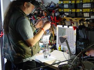
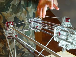
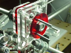
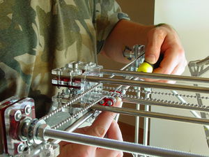
When you're building the X Axis Assembly, assemble the pieces vertically as shown. This makes it easier to keep bits that should stay out of the way out of the way, particularly when fitting the 8mm rods:
You will need the X Motor Assembly, X Idler Bracket Assembly and X Carriage assembly. If using a NEMA17 motor to drive the X Axis, you will need <part a="ifNEMA17">four 8mm diameter 500mm long bright steel rod</part>s. If using the larger NEMA23 motor, you will need <part a="ifNEMA23">two 8mm diameter 500mm long bright steel rod</part>s for the lower pair and <part a="ifNEMA23" >two 520mm bright steel rod</part>s for the top pair to give better stability. There is also an X Opto Bracket to be fitted (it's the one marked "X"...), with an attendant <part>M5 nut</part> and <part>M5 8mm grub screw</part>.
Slide the 500mm rods through the carriage first, as it holds them in roughly the right spacing.
Fit the Opto Bracket before you forget.
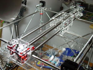
Slide the two end assemblies on, wriggling the rods into the holes in the End Spacers, then adjusting the screws on the Rail Clamps. At some point, standing it on its end as shown above becomes the easier option.
This is what it looks like after it's been fitted to the Y Guide Rails:
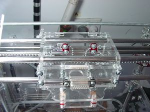
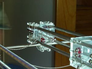
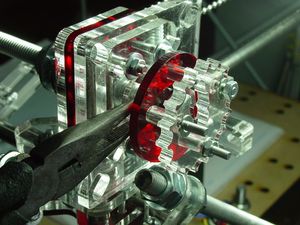
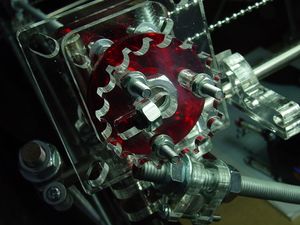
The X stage needs <part>1200mm of 3.5mm ball chain</part>. This shows how the ball-chain is fastened to the X Carriage. Run it around the X Motor Gear, through the slots in the Carriage and End Spacers, around the Idler and fasten using the Carriage clamps.
Use the fixed Clamp to anchor the chain initially, then use the sliding Clamp to apply the final tension and fasten the chain off. Make it sufficiently tight to prevent the chain falling off the Motor gear, but not excessively tight as this makes the Carriage harder to move and increases wear.
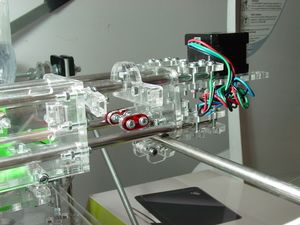
This shows how to fit the Y Saddles onto the Y axis. Make sure both sets of Y saddles are square before you do up the nuts connecting them to the End Spacers. The Y Saddles pull the X Axis Assembly down onto the Y Guide Rails, preventing it from rocking as the Carriage or Y Axis moves.
The green stuff in the left of the photo is a reflection from a Darwin Paste Extruder fitted into the Extruder Socket.
You remembered to fit the X Opto Bracket, right?
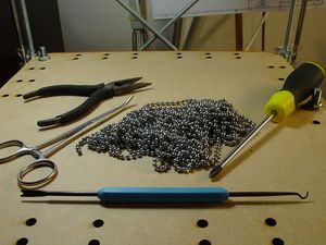
The Y stage needs two lengths of <part p="2"> 1200mm 3.5mm (#6) ball chain</part>, one for each side. You may need a third or fourth hand to get and keep them in place while you adjust them. Locking forceps and bulldog clips come in handy too.
You should have this much chain plus enough to run through the chain clamps. Note that this is NOT the routing of the chain. It goes in-between the X axis rods, with the ends on the bottom side.
One end of the Y Chain fitted loosely into the Y Saddle Chain Clamp.
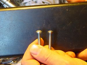
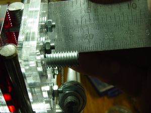
You may need to file down the diameter of the M5 bolt heads to get them to fit snugly into the NEMA 23 motor mounts. The instructions for using NEMA 17 motors haven't been written yet. You're on your own.
Leave 14 mm of Y Drive Rod extending beyond the motor mount bracket. This will give you sufficient room to attach the Y Motor Coupling.
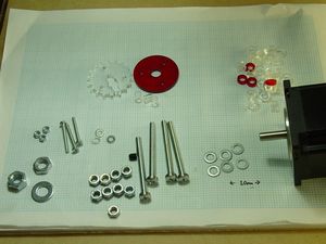
You'll need these parts for the Y Motor Mount.
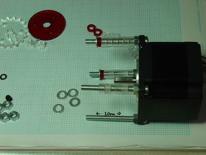
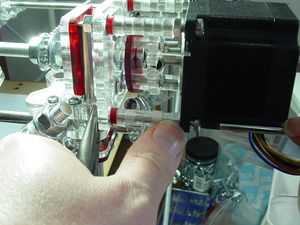
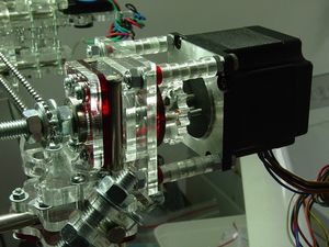
Insert <part>four M5 50mm screw</part>s into the NEMA 23 flanges, and tighten <part p="four M5">nut</part>s on them. The Y motor needs to be mounted some distance away from the Y Drive Rod to leave room for the Y Motor Coupling. Use six M5 spacers cut from 5mm acrylic plus one M5 spacer cut from 3mm acrylic, plus a <part p="four M5">washer</part>.
Put a <part p="3 M3">washer</part> on a <part>3 M3 25mm screw</part>s, and insert them into a 3mm Motor Coupling disc. Using a <part>M8 nut</part>, <part p="M8">washer</part>, and <part p="M8">half-nut</part>, attach the Motor Coupling disc to the Y Drive Rod (remember, you left 14mm of it sticking out).
Put three M3 spacers cut from 8mm acrylic on the screws, the pictured 5mm acrylic ball chain gear with grub slot (or the custom 8mm acrylic equivalent for later kits), <part p="3 M3">washer</part>s, and <part p="3 M3">nut</part>s.
Insert a <part>M5 nut</part> and <part>M5 8mm grub screw</part> into the slot.
Using a <part p="4 M5">washer</part> and <part p="4 M5">nut</part> on the four 50mm screws, attach the Y Motor to the Y Motor Mounting Plate. Rotate the ball chain gear until you find the flat on the motor shaft, and tighten down the grub screw.
Fasten the Y Drive Chain on both sides.
Tighten the Y Saddle Chain Clamps so the X Axis Assembly is square.
| [PonokoRepRap Main Ponoko Page] | ||
| Prev Step | Next Step |
-- Main.VikOlliver - 07 Nov 2008
