HuxleyFrame
General
This page and its peers should guide you through assembling a RepRap Huxley from the TechZone kit, or from parts you have printed which are the same as the TechZone parts. It is a work in progress, and needs some help, feel free to edit this document to add comments of you your own, or contact us [here] and send us messages asking us for better clarification or details.
I am starting by posting the pictures I have, and over the next few days, I will fill in the instructions and details (24 Dec 2010)
Thanks,
Lambert (TechZone R&D/Support/Documenter)
You can access this page and it's peers (for the other parts of the Huxley assembly from the Main Huxley page or from the TechZone Huxley Page
Contents
NOTE: Before starting the Frame assembly, I (Luis Freeman) recommend you review this video [1] and pre-assemble the Y idle belt bearings and others not listed below.
We Assemble the Frame as Units, the Top Unit, the Front Unit and the Back Unit, then we put them together. To begin with, we assemble parts just finger tight, and into aproximate areas. When it is all together, we will fix things by measurements, and tighten them up.
The instructions below differ slightly from the Mendel build instructions, but you can use those as a rough guide for building Huxley as well. Distances will be shorter on Huxley, but techniques and notes will translate over very well. On Huxley, the Mini-Mendel page says that distance J1 is 200mm and J2 is 140mm, but these values are small for the TechZone huxley kit, and are likely small for most Huxleys.
Top Unit
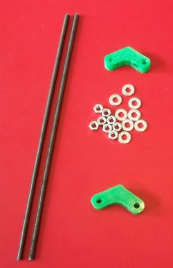
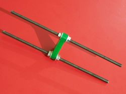
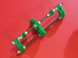
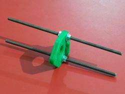
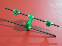
On the left is a picture of the parts used to make the top unit:- (2) of the longest - aprx 295mm (11-5/8") threaded bars from your bar kit
- (8) 6mm nuts
- (8) 6mm washers
- (2) Top Vertices - from the printed parts set
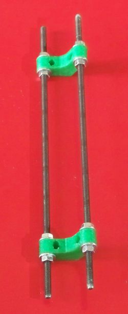
Simply thread the inside nuts onto the bars, then washers, followed by the top vertice pieces, more washers and the outside nuts.
Make the parts just finger tight for now, we will get the exact placement and tighten it up a little more at a later time.
It should look something like the photo on the right when you are done assembling this.
Front Unit
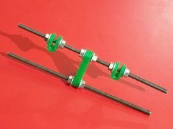
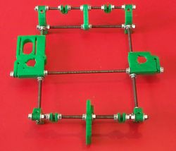
The parts Used to make the Front unit are pictured on the Left, and an assembled front unit is shown on the right. The parts used are:
- (2) Leg Vertices - printed parts
- (1) Y Idler - printed part
- (2) Y Smooth Bar Clamps - printed parts
- (2) threaded rods, two of the four shortest pieces, aprx 210mm (8-1/2") in length
- (16) 6mm Nuts
- (16) 6mm washers
Note: Before starting the front assembly, I (Luis Freeman) recommend to install the "Y" axis belt idler bearings. Two of them are required on the Y idler. To build one belt idler bearing take a 3mm x 30mm cap bolt and insert the following in the order listed: 3mm washer, 6mm washer, 2x 3mm washer, 623 bearing, 2x 3mm washer, 6mm washer, Y idler, 3mm washer, 3mm nyloc. Check to make sure your belt fits. If it doesn't, add extra washers next to the bearing. This assembly is shown about 3 min. 50 sec. from the beginning of this video : [2].
Note (--AlexRa 16:40, 26 January 2011 (UTC)AlexRa): None of the photos clearly shows the correct orientation of the "Y idler" part. It should be installed with the holes for the idler bearings (the short side of the triangle) UP.
Note (--MACB 12:24, 27 April 2011 (UTC)MACB): By accident I noticed that the picture at the bottom of this page under "Put them together" shows the Front Unit on the left side of the picture. If you expand this picture you can see the "Y idler" part in its proper position.
Then add the legs, the inward bend of the legs points the same way as the obtuse angle of the idler triangle, the feet go down, (hopefully they are somewhat obvious).
Back Unit
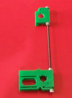
On the left is a picture of the parts used to put together the back frame unit, as shown on the Right. The parts are:
- (2) Leg vertices - printed parts
- (1) Y Motor Mount - printed part
- (2) Y Smooth Bar Clamps - printed parts
- (2) 6mm threaded rod, aprx 210mm (8-1/2") in length
- (16) 6mm Nuts
- (16) 6mm washers
Note: Before starting the back assembly, I (Luis Freeman) recommend to install the "Y" motor mount belt idler bearings. Two of them are required. To build one belt idler bearing take a 3mm x 30mm cap bolt and insert the following in the order listed: 3mm washer, 6mm washer, 2x 3mm washer, 623 bearing, 2x 3mm washer, 6mm washer, Y idler, 3mm washer, 3mm nyloc. Check to make sure your belt fits. If it doesn't, add extra washers next to the bearing.
Put them together
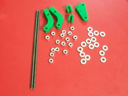
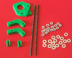
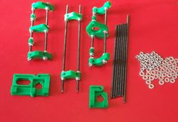
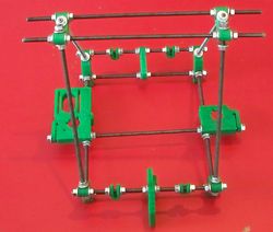
The parts shown on the left are used to put the frame the rest of the way together, most of them you are familiar with by now (having assembled them in the above steps) An assembled frame is shown on the right.
The parts Are:
- Top Unit
- Front Unit
- Back Unit
- (1) Z Axis Combo part
- (1) Z Axis Driven unit
- (6) 6mm Threaded rod to connect the vertices, aprx 245mm (9-1/2")
- (1) 6mm Threaded rod for the Z unit, aprx 295mm (11-5/8")
- (32) 6mm nuts
- (32) 6mm washers
Putting together all the pieces of the frame this way is easiest if you leave some space for all the printed parts to move a little. This way, if they aren't perfectly straight, they can be easily shifted into alignment. Leave them loose until the frame is fully assembled, then start tightening it down. Leave it finger-tight for now, as you'll still need to follow the procedure for squaring the frame. You should be able to follow the instructions on the Mendel squaring axes page with only slight changes to accommodate the size of Huxley.
NOTE: You may find it more convenient to install both Z bearings into the corresponding Z Motor and Z Idler printed parts, before doing anything else with the parts. To fix the bearings, put short bolts (with washers on both sides) into the 3 small holes surrounding each of them.
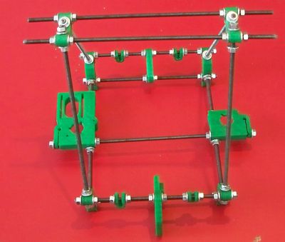
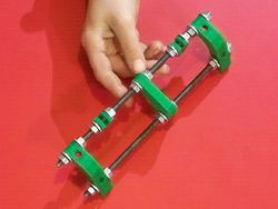
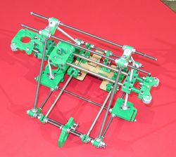
Last, use the four remaining vertice bars to install the top unit to the Base. You should end up with a frame that looks like the picture at the top of this page!
Squaring, and Truing the Size/Shape
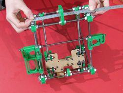
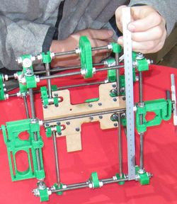
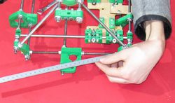
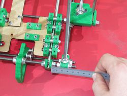
To adjust the frame you simply make lots of measurements and adjust the nuts until all the bars line up where they should be. You can do this as the frame now, and then adjust the Y axis after it is installed, but I like to do them all at once, so I wait until the Y axis is installed then make these adjustments. This is much easier to do if you have the machine on a flat surface. I know this from experience, there was a machine I was building, and I built it on top of all the clutter and tools which had accumulated on my work space... I spent WAY too much time trying to get all the measurements to work.
The front, top and back units are all adjusted to have the same width, as measured on the threaded rod that forms the triangles. I set my bars to 175mm apart, you can use a different number and that is OK, if you go too narrow then the build plate won't fit and if you go too wide the bars won't be long enough. I measure it from center to center on these rods near the vertices. Each unit should be measured near both of the rods that make up that unit. As you adjust the front and back unit, you may need to loosen or tighten the Z bar that is parallel to them in the bottom. I don't ever measure this Z bar, but rather when I have both the front and back units adjusted, I simply snug the nuts for this bar as well (and threadlock it).
After all the adjustments are made on the Frame, I like to put threadlock on, so that the future vibrations won't cause any shifting of the nuts.
Now I adjust the Y axis.
Then I adjust the 180 side so that it fits freely in the 180 bearings for the entire travel of the Y axis. Sometimes, the second bar is not perfectly parallel to the first - this is OK and it is a result of any imperfections in the printed parts in the Y axis. The important thing is to remember that the whole axis will travel the path of the 360 bar, and the 180 bar will keep it from falling, or bumping upwards.
Any nuts or bolts on the Huxley - as it is assembled so far - should now be tightened and threadlock applied if appropriate. (ie, you don't need threadlock on any nylocs, or on the nuts which are embedded in plastic parts)
The Y Motor Mount and the Y Idler are adjusted and threadlocked into place as you install the Y belt.
