Fusionreprap
This page is a development stub. Please enhance this page by adding information, cad files, nice big images, and well structured data!
Release status: Experimental
| Description | Metal Printing Reprap
|
| License | GPL
|
| Author | |
| Contributors | |
| Based-on | |
| Categories | |
| CAD Models | |
| External Link |
Contents
The FusionReprap
The proposed Fusion Reprap uses common metals to fabricate objects. The printer relies on fusion welds (also called forge welds) to deposit layers of metal atop one another. To facilitate this welding process, the printed object is fabricated inside a vacuum(production), or a helium environment(bootstrap).
A sufficient vacuum is achievable with an amateur set-up. A high vacuum is not necessary for this process. Currently, the theory is that good parts in aluminium should be able to be produced in a chamber at equal to or less than 30 Torr. The necessity is for nitrogen, water, and oxygen to be sufficiently rare in the environment of the chamber. Removing oxidation from the metal is also necessary for high quality results. Melting the metal (in the bubbler, stage 2) prior to welding should remove (or at least mobilize) oxidation.
Materials
Aluminum is the test metal. Other materials could become feasible in time.
Construction
For bootstrapping purposes, the printer is divided into multiple stages.
Bootstrapping
The set-up consists of:
- An amateur-quality helium chamber (complete with valves, gauges, and tubing).
- A smaller version of a Rostock robot, fabricated out of PLA or ABS.
- A heater for the extruder capable of melting aluminum. (nichrome wire with a steel core?)
- A wire feed system for the extruder.
- Typical reprap electronics and software (like the Sanguinololu).
- A heated and cooled Build Plate.
Stage 1
- An amateur-quality vacuum chamber (complete with pump, gauge, and tubing).
- A smaller version of a Rostock robot, fabricated out of aluminium on the bootstrap machine.
- A heater for the extruder capable of melting aluminum. (nichrome wire with a steel core?)
- A wire feed system for the extruder.
- Typical reprap electronics and software (like the Sanguinololu).
- A heated and cooled Build Plate.
Stage 2
- An amateur-quality vacuum chamber (complete with pump, gauge, and tubing).
- A smaller version of a Rostock robot, fabricated out of aluminium on the bootstrap machine.
- A heater for the extruder capable of melting aluminum. (nichrome wire with a steel core?)
- A wire feed system for the extruder.
- Typical reprap electronics and software (like the Sanguinololu).
- A heated and cooled Build Plate.
- The Bubbler, a molten metal purification/feeding system.
Vacuum Chamber
Lets begin with a cylindrical chamber. two pressure canners, open-side to open-side, with a thick polycarbonate seal between them. This seal is punctured three times to hold the three corners of the rostock, once for wiring, and once for air removal. The three corner mounts have supports downward, to support the weight of the printer, and so as to not put any of the printer's weight on the chamber.
Modified Rostock
Other than the modifications required for fitting in the limited space, the folowing modifications are going to be made:
- Screw drives instead of belts (this does not need to go fast).
- Tiny nozzle: metal parts that are low precision will likely not be in high demand.
Build Plate
The build plate will be nichrome wire in direct contact with a hexagonal steel sheet(with an empty area in the middle, for the cooler block). Atop that sheet will be a sheet of aluminium or ceramic (for the item to stick to, and to conduct heat away from the item). these sheets will have melted solder inbetween them (for conduction), as well as be attached to each other with binder clips.
The build plate will use ceramic insulation and screws to connect to the bottom bed of the printer. It will also have a liquid cooling core placed in the middle of the bottom of the plate to pull the heat away from the printed object.
The Bubbler
Currently, a bubbler is under consideration for providing metal to the wire feed system. Printing large objects requires a large volume of metal. Stocking the chamber with an adequate amount of metal in the form of wire becomes less practical the larger the printed object becomes. For small prints, a small spool of wire provides sufficient raw material. For large prints, an adequately sized spool of wire may not or cannot fit in the chamber. Restocking the printer during a print requires opening the chamber. This exposure will oxidize the metal already printed, and present difficulties to printing new layers. A metal bubbler provides a solution to these problems.
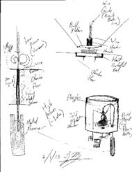
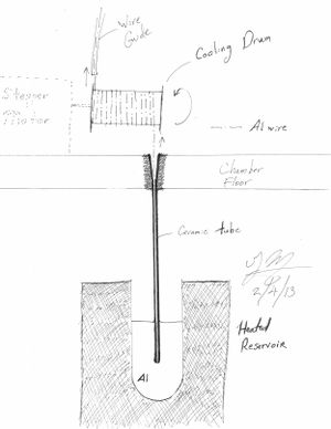
The bubbler system works by continuously casting aluminum from an outside reservoir of liquid aluminum. The outside reservoir heats aluminum to a liquid state. A narrow tube (viz. a ceramic straw) is lowered into the reservoir, so that the tip is beneath the level of the liquid. The tube is open to the vacuum within the chamber. Liquid metal is pushed into the tube by atmospheric pressure, similar to a barometer. As the liquid ascends the tube, it cools and solidifies. The cooled aluminum forms a plug, preventing more liquid from rising. This plug occurs where atmospheric pressure and the weight of the liquid are close to equilibrium. (Finding this point is a matter of fine calculation and experimentation.) A motor mechanically pulls the solid aluminum from the column. The pulled metal is pushed into a wire guide (such as a bicycle brake cable). The wire is then received on the other end of the wire guide, melted, and extruded. By keeping the tube narrow, large demands on cooling can be avoided. Simply put, we're only concerned with a small amount of aluminum. A passive system could provide all the cooling necessary for creating thin, solid aluminum wire from a molten pool.
The advantage of the bubbler system is providing--ideally--all the aluminum necessary for a print without restocking the interior of the vacuum chamber. However, stocking the interior with a spool of wire should be very simple.
Cooling
For general purpose cooling, we're going to use parts from a PC watercooling system, with mineral oil running through them. this is going to be an open system, with mineral oil pooling on the bottom of the chamber. To allow the heat to escape, the chamber's bottom few inches can be submerged in water, or have standard water cooling equipment strapped to it.
For cooling of the plate, we're going to need a two stage solution. the stage hooked to the plate will need a liquid metal cooling solution (solder!), flowing the metal through a coper block. on the other side of the coper block we will pump mineral oil through.
Material Delivery
The extruder is going to be near the top of the printer, delivering material down a tube consisting of a steel coil (bicycle brake cable?). to heat the material, we will be using nichrome wire, wrapped around the carrying tube. A final heating chamber(forge) will be carried on the carriage of the printer.
Developers
- SJ Moquin -- [email protected]
- Julia Longtin -- [email protected]

