CamRap
Release status: unknown
| Description | Documentation of Camrap R&D
|
| License | |
| Author | |
| Contributors | |
| Based-on | [[]]
|
| Categories | |
| CAD Models | |
| External Link |
Contents
Overview
Camrap is intended to be cheap, safe (no high temperatures) and very high resolution.
Key Concepts
Positioning
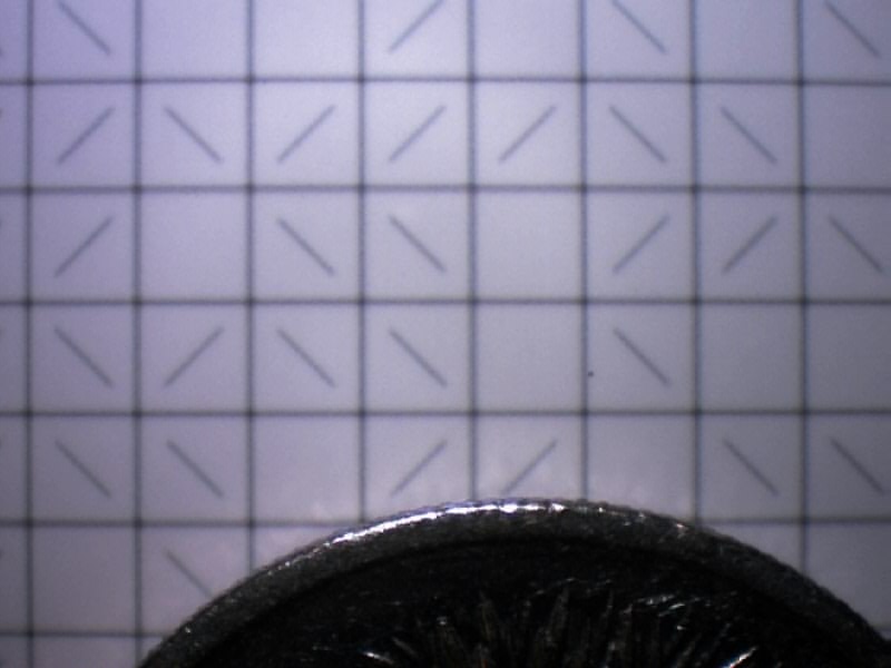
Camrap is named for it's positioning system, which uses a webcam as a means to read a 2d image which encodes X and Y position. Z-axis positioning will likely be "stepped" and have its position inferred as with stepper motors.
The position detection works by processing a captured image of a printed grid, which is attached to the "build platform" and moves with it in X and Y.
The horizontal and vertical line positions can be measured quite accurately by averaging subpixel line positions at each pixel along the line. This determines the image centre point in partial grid units, and the positions of each line in relation to the whole grid can be determined from the diagonal lines. The diagonal lines represent "digits" which can be either /, \ or blank, and each 4*3 sub-grid has a unique pattern of these.
Structure
The current (work-in-progress) prototype Camrap uses 10mm extruded aluminium tube, FIMO polymer clay and some balsa wood as unprinted parts.
The current design is a similar shape to Huxley, but has only single tubes as edges, two of which are also used as X-axis rails. The Y-axis travels with the X-axis carriage.
Printed parts will be some form of polymer clay if possible. "Metal" clays are available which can be fired to remove a binder and leave a sintered metal product behind.
If that doesn't work well enough though, an existing Reprap extruder design could be used.
Because positioning is measured rather than inferred from motor steps or encoder wheels, drive options are not limited to stepper motors. Currently cheap continuous rotation servos are used, but they may prove to be underpowered.
Control Systems
A PC, webcam and an Arduino. Possibly an Android mobile phone could be substituted for the PC and webcam (possibly the Arduino too).
Software
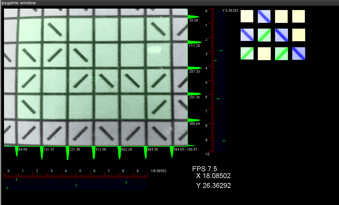 A screenshot of the software used to read 2d position.
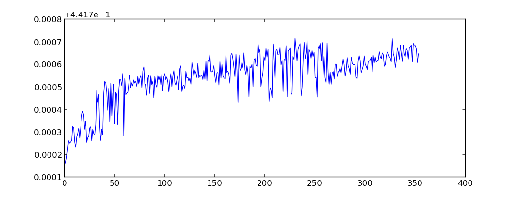
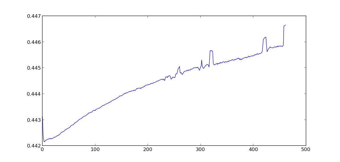
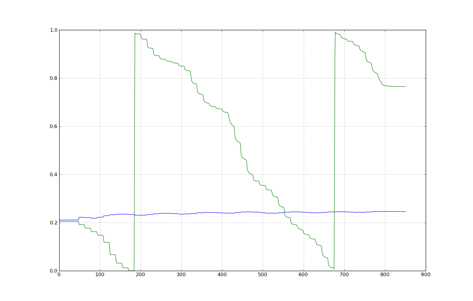
The camera was not moved during this run, so this data is a result of: camera noise, lighting changes, vibration and other errors.
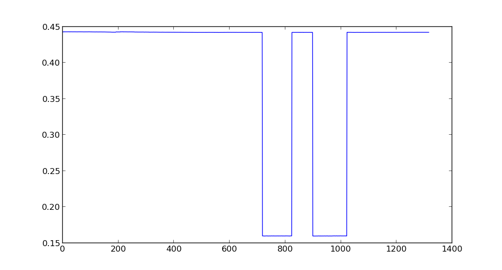
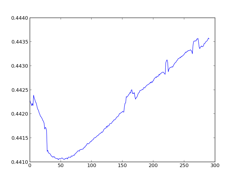
The y axis is 4mm "grid units", x axis is frames.
The camera digital pan function was used to step a few mm and back again. (4mm units again.)
This data is from averaging every 10 frames to reduce noise.
Project log
24 JUN '11
Wiki page with short overview created.
01 MAY '12
Positioning software data and screenshot added.
02 MAY '12
Github repository created.
https://github.com/darkpaw/camrap
README stuff:
The camrap software is written for Python v2.7.
It will capture images of a printed grid with a webcam and report the camera X-Y location based on image analysis.
It needs some python libraries:
pygame numpy scipy PIL
On Ubuntu/Debian they can be installed with:
sudo apt-get install python-pygame python-numpy python-scipy python-imaging
Run it with:
python camrap.py
There are some options for resolution and averaging multiple frames at the top of mainloop.py
The "target" grid can be found in tools as 4mmA3.ps, it should print OK on A4 too.
further reading
- RepRapServo 1 0#active optical position control camera "active optical position control camera"]
- "Pick and Place toolhead" mentions Hough-transform software that might be useful in decoding CamRap images
- "Position calibration & accuracy with a webcam"
- "reliably repeatable positioning"
- "Optical position measurement"
- "Cheapo mouse as shaft encoder"
- "Scaleable encoders"
- "each 4*3 sub-grid has a unique pattern" -- does that make this a Wikipedia: De Bruijn torus, which contains every m-by-n matrix exactly once?
- "a 2d image which encodes X and Y position" is a kind of Wikipedia: digital paper
- Jon Howell uses a similar trinary system with 3 different kinds of squares (he uses black, white, and grey tiles).

