The Original Rroofl
The Original Rroofl
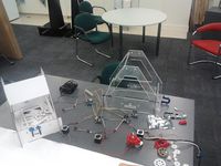
This is how it started at Massey University's FabLab during Fab8nz. Note the lasercut cardboard mockup on the left, which was great for scribbling changes on.
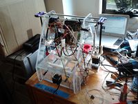
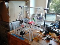
X Axis uses the carriage from the Kiwified Mendel, which went on to become the Prusa. This supports a NEMA17 and 3 x 608Z bearings as corner pulleys; T5 belt does not like corners under tension. Tension in the belt will draw under-constrained Z sliders onto Z guide rods. The X carriage has 4 clip-like printed PLA bearings which give adequate performance on both extruded 9-10mm dia. aluminium tube and drawn steel rod ("piano wire") as narrow as 1/4" and probably narrower under tension. Ideally, these are fitted into the X carriage snugly (use heater and mallet technology) before being slipped on over the ends of the X rails
The X motor and Idler Mounts have slots to allow the X rails to be pinned in place. End stop microswitch is held in place by a single 2mm zip tie or hot-melt glue etc.
Y axis
2mm zip tie used to hold end stop switch in place. Uses 5mm zip ties in the frame to hold both NEMA17 drive motor and the idler. Needs to be measured and the cutting files updated.
Z axis
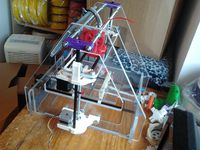
Gears now working even if not well printed. Sockets hold 6 x 608 bearings to support the Z axis drive rods and each end of the Z drive trans-axle. The waterjet cut holes in the frame to support Z brackets need to be +0.5mm diameter and more widely spaced as per the new Z bracket spacings. The gears mesh best with one washer under each of the gears fixed to the Z drive rods. Experiment, and be prepared to grind a few bits of plastic off in pursuit of perfection.
The Z endstop was built into the design by Hamish User:BouncyMonkey, who added a microswitch holder to the Z motor bracket. A length of M8 screw thread to the underside of the X motor bracket pokes the former when the X carriage descends too far. He is also doing pioneering work in creating a sturdy, low-cost, sheetboard frame that local artisans can cut by hand with a scroll saw if necessary.
The deposition bed is a simple piece of 8mm MDF stuck down with double-sided foam, so it needs no fancy holes. Y carriage is in 2 identical parts joined with M8 rod. Y belt secured to carriage with zip ties, which also tension it. It is important to clean the bed's underside before sticking it down.
It looks like we can drop all the holes in the lower part of the frame (and the top edge of both short ends) by about 15mm to increase our build height a bit. If we take another 5mm off the top edges we can claim that back for build height by dropping the height of the Y carriage a bit.
The circuit holding panel needs to move up and away from the build area (printed version does this by using extended length vertex parts), and needs a hole matrix for mounting Arduinos etc. on. If this part is made from MDF or plywood, it is much easier to screw boards into place in while prototyping. It does need to be strong and securely placed, however, as it does actually add considerable structural integrity to the build.
Back to Rroofl


