RepRapPro Mendel wiring
Contents
- 1 This page is under construction
- 2 Goal
- 3 Important: general rules for wiring up
- 4 Tools
- 5 Parts
- 6 Wire routes
- 7 Attaching the control electronics
- 8 The power supply wire
- 9 The heated bed wires
- 10 The X motor wires
- 11 The Y motor wires
- 12 The Z motor wires
- 13 The endstop wires
- 14 The extruder motor wires
- 15 The hot-end ribbon cable
- 16 Connections to the controller board
- 17 Testing
- 18 Next step
This page is under construction
Introduction | Frame assembly | Y axis assembly | X axis assembly | Z axis assembly | Heated bed assembly | Extruder drive assembly | Hot end assembly | Power supply | Wiring | Commissioning | Printing | Multi‑colour/multi‑materials | Colour Printing - Slic3r | Colour Printing - RepRapPro Slicer | Maintenance | Troubleshooting | Improvements
| A notice about these instructions! |
|
Since 1st April 2013, the RepRapPro Mendel has been superseded by the RepRapPro Tricolour and Mono Mendel. |
Goal
By the end of this stage your machine will be ready to commission.
All the wires from electric components in the machine run to the controller electronics.
What you are going to do is to route those wires round the frame from each component to the controller, leaving a generous extra length when the controller is reached and not at that time connecting the wire to the controller.
Then, when all the wires have been attached to the frame with cable ties, you will trim them and make the final connections to the controller.
You can route wires and attach them with cable ties as you go. You will then have to clip off those cable ties when a new wire runs on the same route and add a new one holding both wires. This is slightly wasteful, but easy.
Alternatively, hold all the wires temporarily with sticky tape when you route them. Then go round the machine removing the tape and holding the wires with cable ties when all the wires are in place. This is more fiddly, but more parsimonious.
If you click on the pictures below, you will be taken to a high-resolution version. This will help to make details clear.
If you need to identify wires (there are quite a few) then you can use the type of sticky tape called "invisible" tape. This has a surface that you can write on with a felt-tipped pen. Just put a loop of tape round the end of a wire and write "X-endstop" (or whatever) on the tape. You can either remove your labels when everything is connected and tested (neat) or leave them on (convenient if you dismantle the machine later).
Important: general rules for wiring up
You will do serious damage to your RepRap electronics if the power is connected backwards. Other damaging mistakes are to short out high-current devices like motors and heaters, and to connect high-voltage devices like stepper drivers to signal inputs like temperature sensors.
So - in the sections below where it tells you to check things - please check them thoroughly. It is worth taking the time...
Also important for the steps below: when attaching wires to screw connectors, strip about 5mm of insulation off them, twist them between your fingers, and tin them with solder. The tinning is needed for good contact, and to ensure that fraying does not cause shorts.
When wires leave a device (like a motor) or arrive at a connection (like the screw connectors on the controller) leave a small slack length (about 20mm long) for strain relief - don't have the wires taut.
Finally, when making any changes to the wiring or any other electrical aspect of the machine, first disconnect both the power and the USB.
Tools
- Wire strippers
- Soldering iron
- Small screwdriver
- Vice
You may also need a reel of "invisible" tape.
Parts
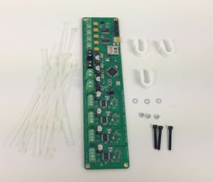
| |
| Item | Quantity |
| Controller board | 1 |
| High-current wire | 0.5m |
| Printed U clips | 3 |
| M3 x 25mm screws | 3 |
| M3 nuts | 3 |
| M3 washers | 6 |
| 3mm i.d. plastic tube | 20mm |
| cable ties | about 60 |
Wire routes
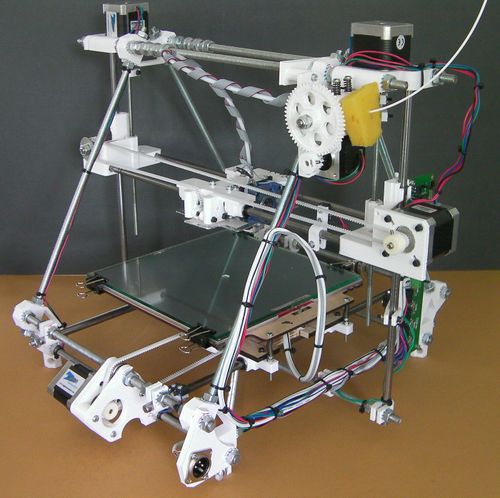
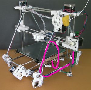
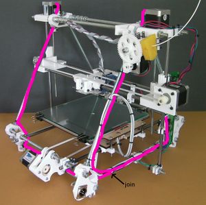
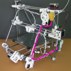
In what follows you will find the routes of the individual connections superimposed on this picture. It is taken from the back of the machine, and the side of the machine on the picture's right is therefore the left side of the machine when it is viewed from the front in its normal working position.
Almost all the wiring runs down the triangle threaded rod to the fore of the picture, and then along the triangle threaded rod at the bottom.
Attaching the control electronics
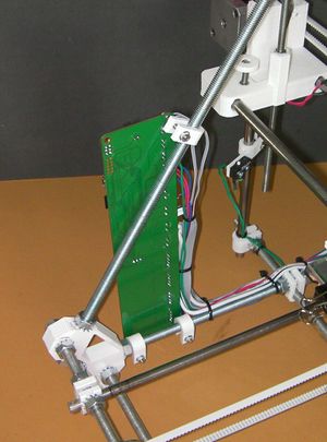
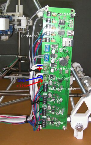
Attach the three U clips to the frame as shown. The controller board goes on the left hand side of the machine at the front (that is, the end of the frame that is on the same side as the XLR power input connector, but at the other end).
Using a sharp blade cut the 3mm internal-diameter plastic tube into three pieces of equal length of about 7mm. These will form spacers between the printed circuit board (PCB) of the controller and the U clips.
Adjust the positions of the U clips so that they line up with the holes in the PCB and the PCB is vertical.
Attach the board to the clips with the screws, washers and nuts. The order goes:
- screw head
- washer
- PCB
- 7mm plastic tube
- U clip
- washer
- nut
Facing the machine from the front, the components on the PCB should be away from the triangle frame and the USB connector and SD card holder should be at the top of the PCB pointing to the front.
The power supply wire
Detach the XLR plug from the frame vertex at the back.
In what follows take great care that there are NO filaments of wire that are sticking out from twisted bundles. These can cause shorts.
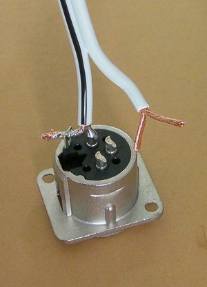
Bare the high-current wire ends, and split each end in two equal halves. Twist those halves separately.
Solder the two from the wire with the black stripe (the Ground - GND wire) to Pin 1 and the plug shell tab.
Solder the two from the plain wire (the +12 volt wire) to Pins 2 and 3.
The pin numbers are embossed on the plug. The picture shows the GND connections made, and the +12 volt connections about to be made. The unsoldered fork in the picture going to Pins 2 and 3 is shown a little long; the bared wires need to be about 2/3 the length shown.
Trim the excess wire from the tab with side cutters.
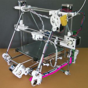
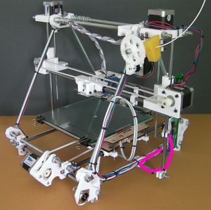
Fit the XLR plug back in the machine. The picture above shows the route of the power wire coloured cerise. Leave a small loop at the XLR plug free for strain relief. Attach it with tape or cable clips to the bottom rung of the triangle, but leave the controller board end free for the moment.
The heated bed wires
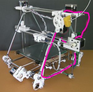
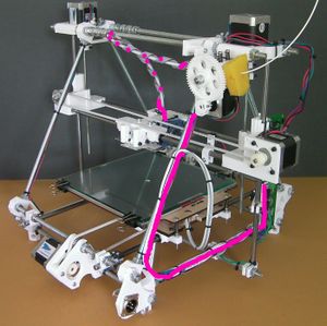
Run the power wire and the thermistor signal wire from the heated bed along the route shown. Cable-tie the two together where they loop free in the air. As you can see, the loop joins the frame about half way up.
Check that the bed of the machine can run freely from one Y extreme to the other without the wires pulling taught and without their catching on anything (particularly the M5 screw that drives the Z axis).
Again, don't attach the wires to the controller for the moment.
The X motor wires
Run the X motor wires along the route shown. (The little bit of cerise colour along the X axis if for the X endstop. That will be done later.)
Leave a generous loop in free air. Remember that the Z axis has to be able to move up and down its full length.
Don't attach the wires to the controller.
The Y motor wires
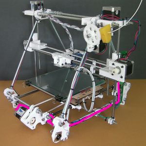
Run the Y motor wires along the route shown. They attach to the bottom threaded rod of the frame at the back. (The little bit of cerise by the Y endstop switch is the wire for that. That will be done in a minute.)
Again, don't attach the wires to the controller.
The Z motor wires
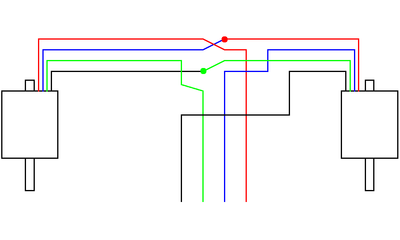
The two Z motors are wired in series as shown in the diagram above. It doesn't matter which motor in the diagram is the left one and which the right - the result will be the same.
Run the Z motor wires along the routes shown. Make the joins where indicated.
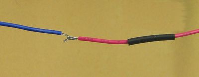
To make the join bare about 10mm of each wire. Put a short length of heatshrink on one. Form each end into a V (blue wire), hook them together, and then close the Vs (red wire). Solder the join (with the heatshrink further away than shown - you don't want to shrink it prematurely).
Move the heatshrink over the join and shrink it with the hot barrel of the soldering iron (don't use the tip - that will make a mess of solder on the outside of the heatshrink.)
The endstop wires
Cut the ends off the motor wires at the controller board end. Make sure you leave a generous length on each to connect to the controller.
Connect your endstops using two wires each. It is a good idea to use a different colour for each axis as this will make it easier to get the endstops connected to the correct input. You should now have plenty of multi-colour wires trimmed from the stepper motors.
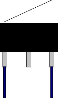
The diagram shows a switch with a lever. RepRapPro Mendel works equally well with levered and un-levered microswitches.
You will probably find it easiest to connect the wires to the endstops with them removed from the machine. Unscrew the three h-shaped clips.
For each endstop switch, crimp or solder a terminal onto the end of the wires, then cover with some heatshrink to insulate the terminal. Connect to the outer pins of the limit switches (the NC = Normally Closed connections; RepRap expects the switch to open when the endstop is hit.)
Put the endstops and their h clips back on the machine.
The X endstop wires
The X endstop wires run along the same path as the X motor wires.
Leave a reasonable loop between the switch and the frame - you may want to adjust the position of the X endstop.
Cable clip all the wires together where they loop free in the air. Get all wires in the loop the same length for neatness (Hint: don't pull the cable ties fully tight. Then you can slide the wires through them to get everything neat before tightening.)
The Y endstop wires
The Y endstop wires run along the last part of the route of the Y motor wires.
The Z endstop wires
The Z endstop wires run along the route shown. Leave a good loop from the switch to the point where it first connects with the frame. You will need to adjust the height of the switch.
The extruder motor wires
Run the extruder motor wires along the route shown.
The hot-end ribbon cable
The hot-end ribbon cable should already be loosely wound round the PTFE filament feed tube.
Attach it to the frame along the route shown.
Connections to the controller board
