RepRapPro Mendel wiring
Contents
This page is under construction
Introduction | Frame assembly | Y axis assembly | X axis assembly | Z axis assembly | Heated bed assembly | Extruder drive assembly | Hot end assembly | Power supply | Wiring | Commissioning | Printing | Multi‑colour/multi‑materials | Colour Printing - Slic3r | Colour Printing - RepRapPro Slicer | Maintenance | Troubleshooting | Improvements
| A notice about these instructions! |
|
Since 1st April 2013, the RepRapPro Mendel has been superseded by the RepRapPro Tricolour and Mono Mendel. |
Goal
By the end of this stage your machine will be ready to commission.
Important: general rules for wiring up
You will do serious damage to your RepRap electronics if the power is connected backwards. Other damaging mistakes are to short out high-current devices like motors and heaters, and to connect high-voltage devices like stepper drivers to signal inputs like temperature sensors.
So - in the sections below where it tells you to check things - please check them thoroughly. It is worth taking the time...
Also important for the steps below: when attaching wires to screw connectors, strip about 5mm of insulation off them, twist them between your fingers, and tin them with solder. The tinning is needed for good contact, and to ensure that fraying does not cause shorts.
When wires leave a device (like a motor) or arrive at a connection (like the screw connectors on the controller) leave a small slack length (about 20mm long) for strain relief - don't have the wires taut.
Finally, when making any changes to the wiring or any other electrical aspect of the machine, first disconnect both the power and the USB.
Tools
- Wire strippers
- Soldering iron
- Small screwdriver
- Vice
You may also need a reel of sticky tape.
Wire routes
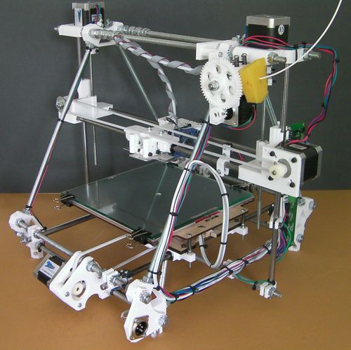
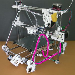
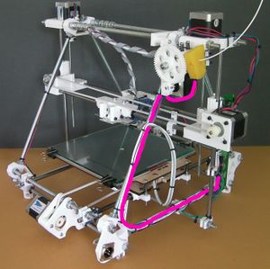
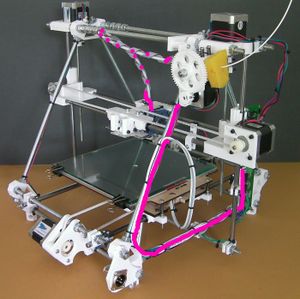
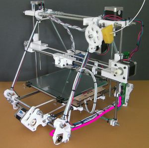
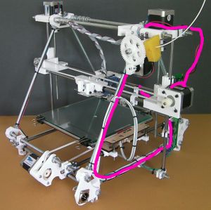
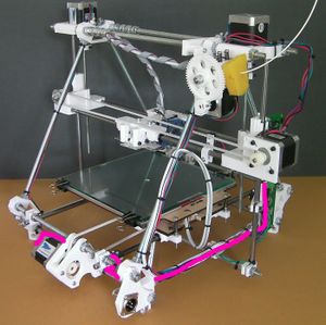
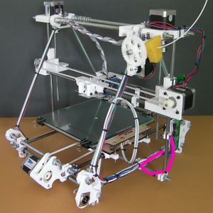
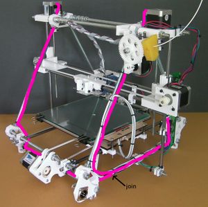
In what follows you will find the routes of the individual connections superimposed on this picture. It is taken from the back of the machine, and the side of the machine on the picture's right is therefore the left side of the machine when it is viewed from the front in its normal working position.
Almost all the wiring runs down the triangle threaded rod to the fore of the picture, and then along the triangle threaded rod at the bottom.
