RepRapPro Mendel heatbed assembly
Contents
This page is under construction
Introduction | Frame assembly | Y axis assembly | X axis assembly | Z axis assembly | Heated bed assembly | Extruder drive assembly | Hot end assembly | Power supply | Wiring | Commissioning | Printing | Multi‑colour/multi‑materials | Colour Printing - Slic3r | Colour Printing - RepRapPro Slicer | Maintenance | Troubleshooting | Improvements
| A notice about these instructions! |
|
Since 1st April 2013, the RepRapPro Mendel has been superseded by the RepRapPro Tricolour and Mono Mendel. |
Goal
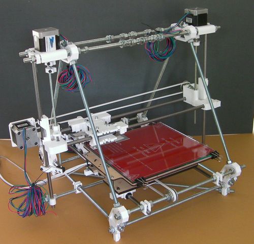
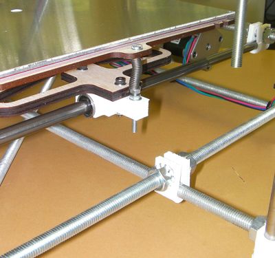
By the end of this step your RepRap machine should look like this:
And in addition it will have an aluminium plate on top of the red circuit board.
Tools
You will need the following tools:
- M3 Allen key
- Cross-head screwdriver
- Multimeter
- Soldering iron and solder
Parts
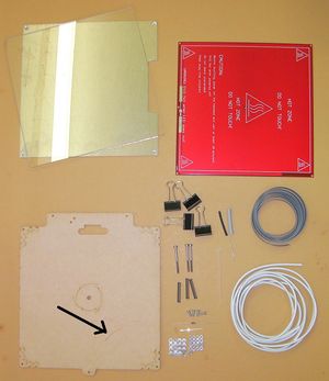
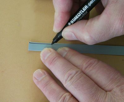
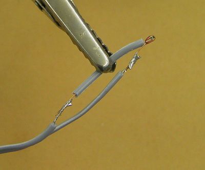
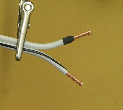
Get the twin ribbon wires by stripping them off the 10-way ribbon cable supplied with the kit. If that ribbon cable has a colored stripe down one side, strip the two wires furthest from it. If it has no coloured stripe, strip from one side, then put the remaining 8-way ribbon flat on the bench and run a felt-tipped marker down one side:
This will make the wires in it easier to identify later. Set the 8-way ribbon aside for later use.
Step 1: Main assembly
Use the countersunk screws together with four nuts and washers to sandwich the heated bed PCB between the aluminium plate and the MDF insulator.
The zig-zag heater track on the PCB faces down towards the MDF insulator.
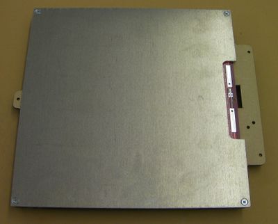
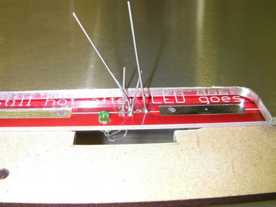
Make sure that the PCB solder terminals, the rectangular cut in the insulator, and the notch out of the aluminium plate all line up.
Take care not to break the lasercut springs in the corner of the insulator. (These are to allow for differential expansion.)
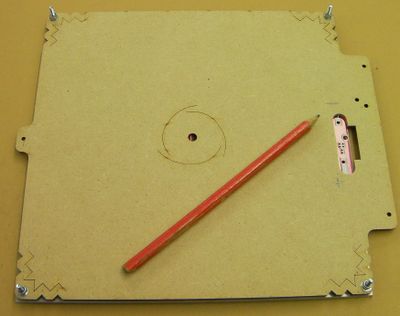
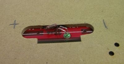
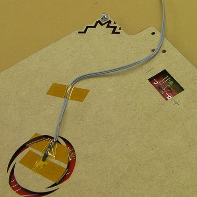
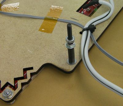
Here is a view of the underside. Use a pencil to mark + and - as shown. This will help with the wiring.
