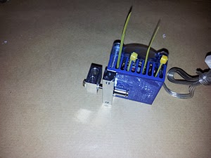
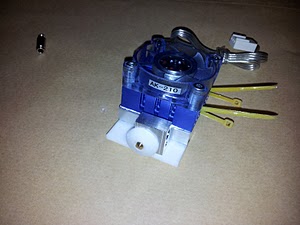
RepRapPro Huxley hot end assembly
| Introduction | Frame assembly | Y axis assembly | X axis assembly | Z axis assembly | Heated bed assembly |
| Extruder drive assembly | Hot end assembly | Installing the electronics | Wiring | Commissioning | Printing | Troubleshooting |
Contents
This page is under construction
Goal
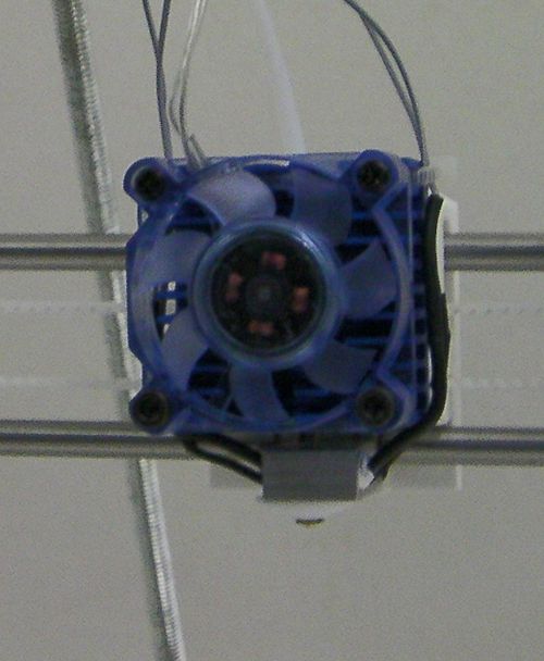
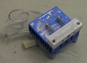
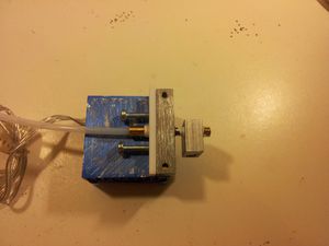
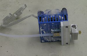
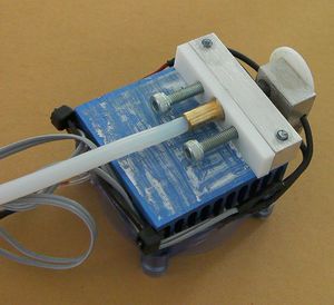
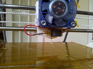
By the end of this stage you will have finished all the mechanical construction! Your hot end will be fitted to your Huxley like this:
Tools
You will need the following tools:
- Allen key
- Small screwdriver
- Pliers
- Adjustable spanner
- Heat sources (small blowtorch plus hairdryer/soldering-iron)
- Bench vice
Parts
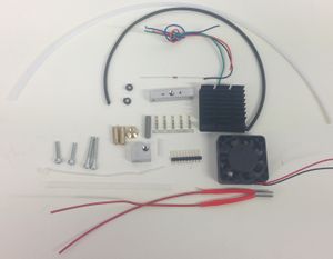
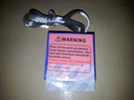
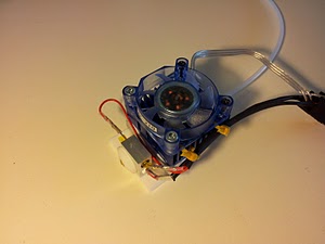
Sharp eyed readers will notice that the PTFE rectangle with two holes in the loop of wire in the picture is not in the list on the left. It is an old part that may still be in your kit. It is no longer needed.
The hot part of the hot end
Take the PTFE tube from the extruder drive that you just made. Cut a short length (about 15mm) from its free end using a sharp blade, taking care to make the cut square on to the axis of the tube. Put the short length aside for use later.
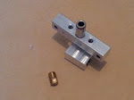
Screw the brass union onto the end of the PTFE tube that you have just cut. By looking down the other end of the brass you will be able to see when the PTFE reaches the end of the thread.
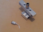
Follow these instructions to prepare your thermistor.
Step 2: Assemble the machined parts
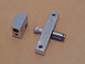
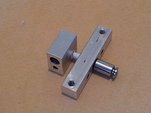
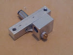
Screw a pneumatic fitting into the heatsink block by hand as far as you can. Coat the countersunk end of the barrel in heatsink compound and screw this into the other end of the heatsink block, again by hand until it butts against the pneumatic fitting.
Now unscrew the pneumatic fitting by up to 1/2 a turn, then screw the barrel in a little further until it stops. Now tighten the pneumatic fitting by gripping its outer diameter with a pair of pliers.
Wrap some PTFE plumber's tape around the free end of the barrel, ensuring you wrap in the direction of the threads, so that when you screw the barrel into the heater block, the PTFE tape stays in place.
Screw the heater block onto the barrel to the end of the thread. NOTE the orientation of the heatsink block in the image above.
NOTE: Before fitting the brass nozzle, it is worth ensuring the inside is clean. Although a contaminated melt chamber will not break your machine, it will likely cause failed prints.
Wrap the nozzle in PTFE plumber's tape, again ensuring it follows the direction of the threads, and screw this into the open end of the heater block, by hand, until it butts against the barrel.
Hold the heater and heatsink blocks in one hand, ensuring they are parallel, then tighten the nozzle using the pliers. Do not try to overtighten at this stage, the trick comes next, (if you do not like the idea of the following instruction, there is an alternative solution which will be given after the hot end is wired and connected to the electronics).
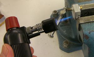
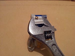
Hold the heater block with an adjustable spanner (mole grips would also work), and heat the heater block with the blowtorch.
This needs to be a powerful heat source as you need to heat the Aluminium heater block enough for it to expand by at least the amount it will expand during printing. Neither the brass nozzle nor the stainless steel barrel will expand as much as the Aluminium heater block, so whilst hot and holding the cold end of the spanner, tighten the nozzle with the pliers. This will normally take only a very small amount of rotation (say 1 or 2 degress) but will be enough to ensure the nozzle assembly does not leak during printing.
Step 3: Attach the fan assembly
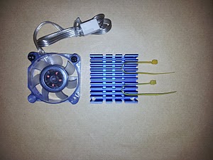
Prepare the fan assembly by removing the adhesive tape from the back face of the heatsink. DO NOT discard this tape as it can be cut and used to attach the SMD heatsinks to the A4988 stepper driver ICs.
Fit a couple of zip ties between the fins (which will later be used to secure the hot end wiring).
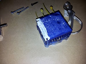
Now spread a thin layer of heatisnk compound on the back face of the heatsink between the 3.2mm diameter holes.
Using 2 M3x25mm screws to attach the fan assembly to the heatsink block, with the heatisnk block protruding below the fan assembly.
Step 4: Fit the heat shields
The PTFE heat shield attaches to the heatsink block using the 2 M3 countersunk screws and is stood off the block using an M3 washer over each hole.
The heat spacer (the PTFE strip with 3 holes in it) slides over the pneumatic fitting and has an M3x16mm screw fitted in each of the outer holes. These screws should only be screwed in a couple of turns as they are used to mount the hot end to the nozzle mount on the X carriage.
The final step is to screw the PTFE nozzle shield onto the nozzle.
NOTE: the nozzle must protrude beyond the PTFE nozzle shield.
If this is not the case, cut some material from the nozzle shield with a craft knife (PTFE is quite soft). If the nozzle shield will not screw right up to against the Aluminium heater block, cut some material from the bottom of the PTFE shield plate.
Step 5: Add the electrical components
The power resistor can now be fitted inside the heater block. This needs to be a push fit into the hole, so if it's a little loose, wrap a small amount of Kapton tape around the resistor and push it into place. Trim the resistor wires to about 10mm in length.
Assemble your thermistor as per these instructions, leaving the PTFE insulated wires approximately 90mm long.
For the resistor wires, cut one to 90mm in length, and another to 120mm. Crimp or high temperature solder a crimp terminal onto one end of each of these wires, and insulate with a short length of PTFE heatshrink.
Fill the thermistor hole in the heater block with heatsink paste, then push the crimp terminals onto the resistor wires, push the thermistor into its hole, and secure all of the wires using the two zip ties which were earlier fitted between the fins of the heatsink. Using two zip ties ensures the wires do not snag on other machine components during printing, and also ensures the thermistor remains in the hole.
Crimp or solder a male pin onto each of the free wire ends, then push these into the female 6-way molex connector.
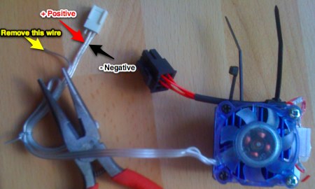
Cut the fan wires to a suitable length, and fit a male pin onto the two leftmost fan wires (when looking at the fan as from the image below).
Alternately working from the plug end see picture below:
Push these into the last two positions of the female molex connector. The leftmost wire in the diagram above must be connected to ground, and the central wire to 19v.
