RepRapPro Huxley heatbed assembly
| Introduction | Frame assembly | Y axis assembly | X axis assembly | Z axis assembly | Heated bed assembly |
| Extruder drive assembly | Hot end assembly | Installing the electronics | Wiring | Commissioning | Printing | Troubleshooting |
Contents
Goal
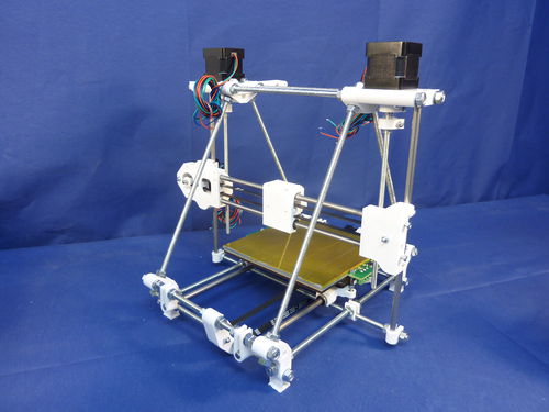
By the end of this stage, your machine will look like this:
Tools
- Wire cutters
- Soldering iron
- Allen key
Heated bed assembly
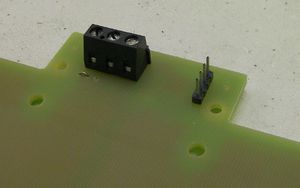
Start by soldering the connectors in place. The wire holes on the screw connector face outwards. Also use the length of wire to make a jumper between the left two holes beside the 3-way screw connector:
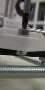
Use one of the M3x10mm screws with a washer under its head to pull the nylock nuts into the three hexagonal recesses under the printed parts of the Y sled:
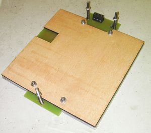
Sandwich the flat components together. This shows them upside down to the way they will be when fitted to the machine:
The aluminium plate has a recess in the centre to accommodate the tiny surface mount thermistor in the middle of the PCB. You can put heat-sink grease in that recess to improve the thermal contact between the thermistor and the aluminium plate if you like.
From the top down in the picture they go:
- Balsa ply insulator (lasercut lettering downwards)
- PCB (circuit side down)
- Aluminium plate
Take care when sandwiching the parts together that the edge of the recess does not hit the thermistor - you don't want to knock it off...
Put washers under the heads of the four short M3 screws and screw them through the stack from underneath to hold it together. Don't do the screws up so tight that they project through the aluminium plate. The ends of the screws need to be just below the plane of the top of the plate. If they project, put extra washers under their heads.
Use the 35mm screws to attach the heated bed to the machine. The springs go between the PCB and the printed parts of the Y sled. Put a washer under each spring where it bears on the printed parts of the Y sled.
Don't do the screws up too tight - they should just compress each spring by a millimetre or two.
Carefully run the Y-axis back and forth by turning the toothed pulley on the Y motor by hand. Make sure that nothing hits anything.


