RepRapPro Huxley Melzi wiring
| Introduction | Frame assembly | Y axis assembly | X axis assembly | Z axis assembly | Heated bed assembly |
| Extruder drive assembly | Hot end assembly | Wiring | Commissioning | Printing | Troubleshooting |
Contents
- 1 This page is under construction
- 2 Goal
- 3 How to damage your RepRap electronics very badly
- 4 Tools
- 5 Wire routes
- 6 Step 1: The PTFE tube shield
- 7 Step 2: The controller
- 8 Step 3: The steppers
- 9 Step 2: Endstops
- 10 Step 1: Motors
- 11 Step 3: Heatbed
- 12 Step 4: Hot end
- 13 Step 5: Jack connector
- 14 Next step
This page is under construction
Goal
By the end of this stage your machine will be ready to commission.
The electronics will have been temporarily fitted. This allows wire lengths to be set and the machine to start working. Its first print will be the final parts needed to build itself: the clips for holding the controller PCB and the power socket.
You will then remove the temporary attachments and replace them with permanent ones.
How to damage your RepRap electronics very badly
The best way to do this is to connect the power backwards. Other good ways are to short out high-current devices like motors and heaters, and to connect high-voltage devices like stepper drivers to signal inputs like temperature sensors.
So - in the sections below where it tells you to check things - please check them thoroughly. It is worth taking the time...
Tools
- Wire strippers
- Soldering iron
- Small screwdriver
- Vice
Wire routes
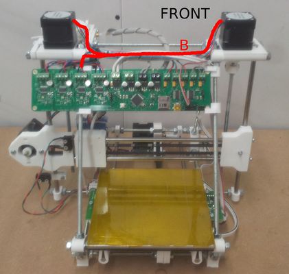
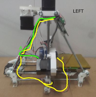
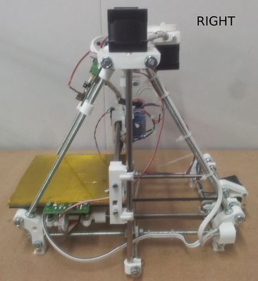
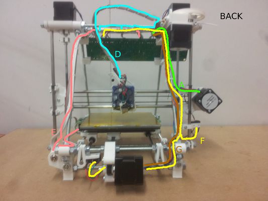
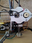
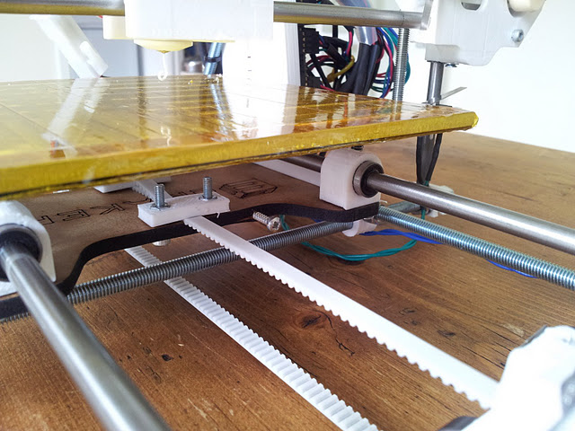
These elevations show the wire routes round the machine. They are referred to in the individual sections below.
The wires will ultimately be attached using coil strip and cable ties. But at this stage attach then using sticky tape (the tape called "pressure tape" works well). If you do this you can build things up incrementally without sacrificing ties when you need to move a wire.
Step 1: The PTFE tube shield
Run a length of the curled wire retaining strip along the back M6 threaded bar at the top. This should completely cover the threads. It prevents the extruder's PTFE tube from rubbing on them.
Step 2: The controller
Take a piece of thick cardboard and draw round the main contoller PCB on it. Cut out the shape with scissors.
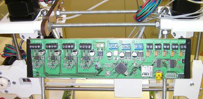
Tape the main contoller PCB and the cardboard to the top of the frame as shown. First tape the card to the frame on its own, then tape the PCB to that.
Offset the PCB so that the USB connector (yellow in the picture) is just to the left of the right-hand angled threaded bar.
Important for the steps below: when attaching wires to the controller's screw connectors, strip about 5mm of insulation off them, twist them between your fingers, and tin them with solder. The tinning is needed for good contact, and to ensure that fraying does not cause shorts.
Step 3: The steppers
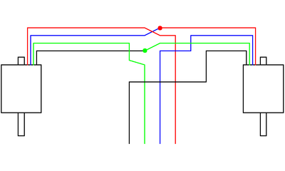
Start with the Y stepper wires. These follow route G on the pictures above.
Step 2: Endstops
Connect your endstops using two wires each. It is a good idea to use a different colour for each axis as this will make it easier to get the endstops connected to the correct input.
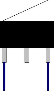
For the limit switch end, crimp or solder a terminal onto the end of the wires, then cover with some heatshrink to insulate the terminal. Push these onto the outer pins of the limit switch.
For the other end of the wires, again crimp or solder a terminal onto each wire, then push into the outer positions of a 3 way female connector. Push this onto the relevant endstop input header pins (either way round).
Note: The endstop wires should be twisted lightly to reduce inductive "noise" coming from the stepper wires. You should also route the endstop wires separated from the stepper wires. Make sure the Y-stop wires don't hit the frog and the bearings.
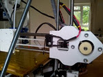
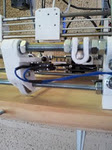
The endstops should be mounted as per the images below
The endstop switch holes should be drilled out to 3mm diameter so they can be mounted using #4x1/2" self tapping screws (alternatively, #2-56 and M2.2 screws will fit the switch, but are not included). The X and Z stops will work without any other modification, but the Y stop requires something sticking out of the frog for it to touch; a self tapping screw will allow you to adjust it later to make the home position match the corner of the bed.
Step 1: Motors
The motors have been provided with 1m long wires. This is more than is required to connect the motors. The surplus may be used to connect the endstops and thermistors.
Route your motor wires to the Sanguinololu board, and cut them to the required length (keep the spare for later use). Crimp or solder a terminal onto the end of each wire, then push each wire into a 4 way female connector in the sequence shown below; you should hear a tiny "click" as the terminal latches into the housing. Always give the wire a little tug to make sure its latched; they will slide back when you try to plug them in if they aren't latched. If you need to pull out a terminal, lift gently up on the little plastic finger that bears on each termial and you can pull it out. If you need to buy more pins, they may be Molex SL (stackable linear 70058) series. There are lots of female pin part numbers, but this one should do the job: SL™ Crimp Terminal 70058, 24-30 AWG, Reel Selective Gold (Au) from Molex.com. Lots of companies stock and sell these.
The correct order is Blue - Red - Black - Green with green in the most right hole of the connector, marked with a little arrowhead.
Plug the motor connector into the matching output header pins. Ensure the connector is fully seated on the pins.
Step 3: Heatbed
Assemble the heatbed wiring loom as per the instructions on the heatbed assembly page.
- Nichrome to the corresponding screw terminal
- Thermistor to the corresponding molex marked "b-therm" (opposite side of the screw terminals, so prepare your wire to have more length for one or the other)
Step 4: Hot end
- Resistor to the corresponding screw terminal
- Thermistor to the corresponding molex marked "e-therm"
- Fan to the two position molex by the "E-Motor" connector; +12 is the pin closest to this connector.
Step 5: Jack connector
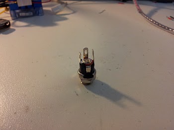
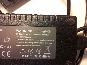
The power from the 19v power supply comes through the connector with positive in the centre and negative around the outside
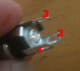
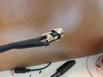
You need to solder one wire to the leg which is connected to the central pin (number 3 below), and one wire to the leg which is connected to the outside contact (number 1). The extra outside contact is a switch that opens when you plug in a power supply. If you are not sure which one is which, plug the power supply in and check which pins are powered with a voltmeter. You can avoid the whole question by simply connecting BOTH outside contacts to the negative wire (number 1 and 2). A short length of black heatshrink may be slid over each of the two soldered legs to electrically insulate them.
The wire coming from the central positive pin should be screwed into the positive side of the Sanguinololu's power screw terminal. The other wire is to be screwed into the side marked GND.
/!\ Pay attention to not invert your power supply otherwise it will probably blow the big capacitor (1000µf) and/or other things.
The fan comes with a molex connector on it. Using a needle, push down gently in the little slot on the side of the connector to free the latch and slide each pin out one at a time. These pins are diffent from the ones used on the steppers! Slide them back into the white connector body that came with the fan in the SAME orientation they came out; they only go in one way! The correct order, with the slots down on the table, the wiring holes pointing toward you, and the two orientation tabs looking at you, is Red, Black, then Yellow. It plugs into the end pair of pins on the row of double molex headers; the micro SD card goes on the end toward the mounting screw hole. When it is plugged in correctly, the red wire is on the side toward the Pololus. The red wire goes on a pin labelled "12V". The orientation tabs and the connector design make this the ONLY direction that it can be inserted.
