Prusa i3 Build Manual
|
English • العربية • български • català • čeština • Deutsch • Ελληνικά • español • فارسی • français • hrvatski • magyar • italiano • română • 日本語 • 한국어 • lietuvių • Nederlands • norsk • polski • português • русский • Türkçe • українська • 中文(中国大陆) • 中文(台灣) • עברית • azərbaycanca • |
Contents
Single Sheet Frame Style
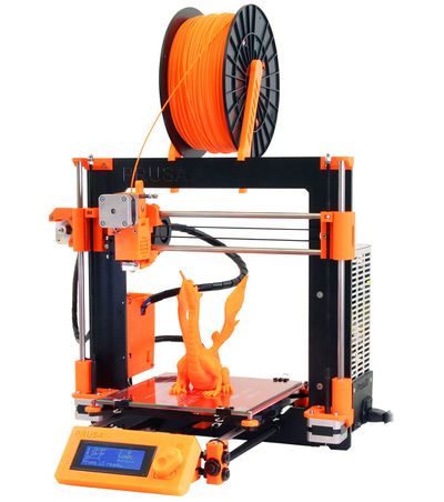
http://www.flickr.com/photos/prusajr/8107645350/in/photostream
To reduce confusion, documentation of the EiNSTeiN variant has been moved to here http://reprap.org/wiki/JBFromOZ.
Official vanilla Prusa i3 build manual by Prusa is available at http://prusa3d.dozuki.com/c/Prusa_i3_kit
Materials
Single plate Version Rods: - updated to numbers from https://github.com/josefprusa/Prusa3/blob/master/box_frame/doc/dimensions.md
X Axis;
- 2x 370mm M8 smooth rod
- 1x 20mm M8 smooth (for extruder idler, use 8x20 threaded rod or grub screw instead as substitute)
Y Axis;
- 4x 205mm M8 threaded - Note 210mm for nyloc nuts. If they are cut to exactly the same length will make assembly easier.
- 2x 350mm M8 smooth rod - Note take care to cut to exactly same length.
- 2x 380mm M10 threaded - Note M10 is correct.
Z Axis;
- 2x 320mm M8 smooth rod.
- 2x 300mm M5 threaded (or 320mm if you want it to protrude above the frame).
Rod Lengths:
http://titanpad.com/bU77NESnMC
In summary:
| M5 Threaded | M8 Smooth | M8 Threaded | M10 Threaded |
|---|---|---|---|
| 2 x 300mm | 2 x 370mm | 4 x 205mm | 2 x 380 |
| 1 x 20mm | |||
| 2 x 350mm | |||
| 2 x 320mm | |||
| 600mm | 2100mm | 820mm | 760mm |
Note: Last row shows totals for each size/finish
Boxed style Frame Style
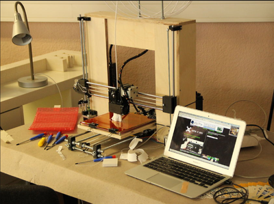
In the future this page might contain a tutorial. Until then, a tutorial for the boxed frame style Prusa i3 by Kliment:
Rods
note check here for detailed instructions for where these numbers are derived from https://github.com/josefprusa/Prusa3/blob/master/box_frame/doc/dimensions.md
X Axis;
- 2x 470mm M8 smooth rod
- 1x 20mm M8 smooth (for extruder idler, use 8x20 threaded rod or grub screw instead as substitute)
If you want to play with the X length, you will have to cut the top (longest) plate as long as the smooth rod and one of the 450mm is actually (X rod length - 2x plate thickness) long. The rods may be longer, but should not be shorter by more than 1cm
Y Axis:
- 2x 370mm M8 smooth rods
- 2x 400mm M10 threaded rod
-
2x 400mm M8 threaded rods(M10 is actually correct) - 4x 205mm M8 threaded rods
Z Axis:
- 2x 405mm M8 smooth rod
- 2x ~370mm M5 threaded rod
You could play with the Z lengths to increase building height.
For this you will need longer wood cut for 4 of the 450x100mm plates; The plates are (Z rod length + 45mm) long
Frame
Default is 12mm thick wood. Get something that is strong and not likely to warp (change shape) due to temperature and humidity! The thickness is mostly needed to hold the screws used hold the frame together and to mount parts onto it. The entire frame structure must be stiff, holding its shape regardless of what it's sitting on.
- 6x 450x100x12mm wood
- 1x 475x100x15mm wood
Any wood _over_ 12mm thickness will not work for the bottom plate with default config, the Y will then be lifted from the ground.
So if you are using thicker wood for the frame, be sure to change board_thickness in configuration.scad before printing parts
==
The first design choice is between the boxed style frame and the single sheet (also called single plate) style frame. The box style is somewhat more rigid, but also slightly more complex to build and less aesthetically appealing. Single sheet frame is simple, but uses expensive laser cut aluminum parts. (more info here) Note that the two frames require different length rods. For info on the rods, or on using different length rods to increase/decrease your build volume, look here.
The exact width of the boards is not crucial, so long as the lengths are appropriate to the rods used. (Note that the width of the bottom board limits how far forward the y axis can be placed. This is compensated for by offsetting the linear bearings on the y carriage/bed.) If different board thicknesses are used, the design will have to be modified slightly.
The y axis M10 threaded rods should just clear the bottom of the frame in order for the printed attachment points to sit at roughly the right level. The frame width (475mm) should be 5mm longer than the x axis smooth rod length (470mm).
The 475mm board is longer so that it can span the whole frame width and overlap two other boards, which are 12mm thick. (450 + 12 + 12 ≈ 475mm)
Box Style Frame Part
Sourcing Options
Source
6x 450x100x12mm pieces of wood (If bottom board is more than 13mm thick, it will bow the y axis up.) cut from three boards, each 48x4x1/2"* Home Depot, Lowe’s, etc. cut from one sheet 24x48x1/2" plywood*
475x100x12mm piece of wood (if using boards that are not 12.5mm thick, adjust length to be 450 plus twice the thickness) cut from one 48x4x1" board*
cut from one sheet 24x48x19/32" plywood* Home Depot, Lowe’s, etc.
230x230x12mm wooden bed cut from a 10x1" thick board* Home Depot, Lowe’s, etc.
cut from one sheet 24x48x1/2" plywood* Do it Best, Home Depot, Lowe’s, Wickes, etc.
60x 3.5x20mm wood screws #6 x 3/4” wood screws Do it Best, Home Depot, Lowe’s, Wickes, etc.
Glue (optional) Wood glue Local hardware store
Wood Sealant (optional) Assorted shades and colors Local hardware store
- Actual dimensions of lumber are smaller than nominal due to shrinkage during drying. Some given dimensions are actual, and some are nominal.
Wood also warps as humidity changes. To minimize this, select pieces with uniform edge-grain without knots. Oak and poplar are good choices. (More information on wood selection here). Using a wood sealant will minimize changes in moisture content. A thin, light, unsealed wood should be used for the heated bed. A heavy bed will limit print speed and quality, and the heat will break down the sealant. Even paraffin wood sealants designed for saunas wouldn't be able to keep steam from leaving the surface if it gets close to 100°C. It would, however, prevent moisture from returning to that surface after cooldown. Uneven moisture content is what CAUSES warping, so this is a bad idea.
Parts to be Purchased
BOM
There are a number of variants of i3 single plate.
The original Prusa variant BOM is located at https://docs.google.com/spreadsheet/ccc?key=0Aga03tFhujeidDJzR0ZJNFZQYkhXTXlWd1BLRkN4Nmc&usp=sharing
The JBFromOZ BOM, RP list and build info on his EiNSTeiN variant is here
The current BOM used by BotBuilder.net for their workshops is located here: http://www.botbuilder.net/documentation - Updated Oct. 2013.
The Sourcing Your Own Parts section of the i3 buyer's guide is an attempt to make a comprehensive parts list, with links and info on ordering individual components.
Rapid Prototype Parts
| Description | Qty | Image |
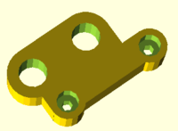
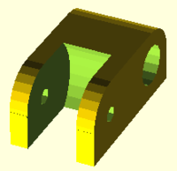
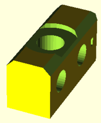
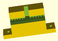
| RP Parts | located in Prusa/single_plate folder | |
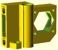
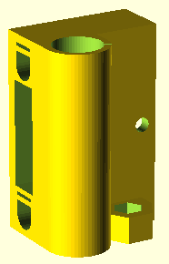
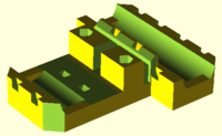
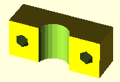
| z-axis-top.scad preview | 1 | |
| z-axis-bottom.scad preview | 1 | |
| y-motor.scad preview | 1 | |
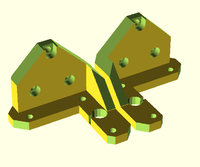
| y-idler.scad preview | 1 | |
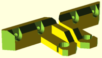
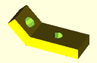
| y-corners.scad (M10 x 1 M8 x 2 holes) preview | 4 | |
| y-belt-holder.scad preview | 1 | |
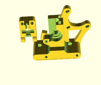
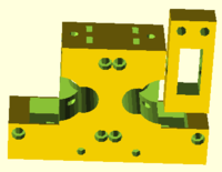
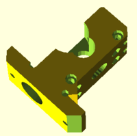
| x-end-motor.scad preview | 1 | |
| x-end-idler.scad preview | 1 | |
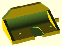
| x-carriage.scad preview | 1 | |
| magnetic-holder.scad (used for hall effect sensors / endstops) preview | 2 | |
| fan-mount.scad preview | 1 | |
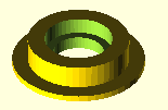
| belt-guide.scad (suit 623 bearing) preview | 4 | |
| Extruder options | not complete documentation at this stage | |
| gregs-wade.scad (in box_frame/extras folder) preview |
1 (???) | |
| greg-adapter.scad (in mini/extruder/greg-wade folder) | 1 (???) | |
| dual-extruder.scad (deprecated - experimental) | 1 (???) | |
| compact-extruder.scad (experimental - likely to be replaced by nema17 extruder) | 1 (???) | |
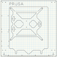
| Single-Frame i3 | Aluminium 6mm plate 370mm x 370mm | |
| Prusa3ALU-FREZOVANY-v4.dxf | 1 |
Note:
The Prusa3 repository (below) includes frames for both aluminum and laser cut wood (sized for 6mm thick) for both the "single_plate" and "mini" variants. The wood frame files include two gussets, which stabilize the frame from flexing. Photos of each can be found at:
"single_plate": http://www.flickr.com/photos/sbgraber/sets/72157632513929965/with/8378333341/
"mini": http://www.flickr.com/photos/sbgraber/sets/72157632518684272/with/8379471692/
The Prusa3ALU-*.dxf and Prusa3WOOD-*.dxf feature y-carriages that use zipties to fasten three LM8UUs to the underside. Prusa3_SC10UU-*.dxf has mount holes for SC10UU linear bearing blocks. Use whichever carriage fits your need.
File Sources
Github
- https://github.com/josefprusa/Prusa3 - Josef Prusa - main development repository - scad file sources only available
- https://github.com/alexrj/Prusa3/tree/i3-unterwelt - Sound MINI repository, MGS extruder repository (files for parts shown above) - scad file sources and stl files available
- https://github.com/EiNSTeiN-/Prusa3/ - EiNSTeiN - 608 bearings, compact dual extruder repository, note that Y ends for M10 not M8 rods - scad file sources only available
- https://github.com/josefprusa/Prusa3-vanilla/tree/master/distribution - vanilla - used by josef prusa in his workshops - scad file sources and stl files available
- https://github.com/Joaz/machine_parts/tree/master/mgs_prusa - Joaz - MGS extruder repository (parts not shown above)
- https://skydrive.live.com/?cid=61d9a16368c58a74&id=61D9A16368C58A74!107&ithint=file,.rar&authkey=!AOcaZeSUEgaTCBA - 3D Printer Czar - STLs with improved Y belt holder
STLs:
- Einstein stls: singleplate -->>File:Einstein-singleplate-stl.zip (generated 19/2/2014)
- Einstein stls: boxframe -->>File:Einstein-boxframe-stl.zip (generated 19/2/2014)
- vanilla stls:File:I3vanilla.zip
NOTE: developers are encouraged to link or post their sources but also printable stl files, currently (19/2/2014) some of the scad files are throwing errors or missing variable names or simply don't generate anything, instructions for generating stl files from scad files are unclear in terms of which ones to use, the above stl zip files may or may not be accurate however it's better than the previous situation,there are more zipped stl files to be done - thejollygrimreaper
Other Build Documentation
- Acrylic frame build document by 3D Printer Czar: https://skydrive.live.com/redir?resid=61D9A16368C58A74!113&authkey=!AI2iTJjJC1ZxdG0&ithint=file%2c.pdf
- Single plate build pics: http://www.sub-design.co.uk/i3build/
- Prusa i3 Frame Kit Build Manual by ReprapUniverse.com: http://dl.dropboxusercontent.com/s/femvh8j5njf4sag/prusa_i3_frame_kit_build_manual.pdf
- Build Documentation: http://78.47.92.212/i3_documentation_pics/
- BotBuilder.net Workshop Build Documentation - (50 page PDF)
- Build Videos
Build instructions of singe plate as an interactive animation
- [[:File:Linux.zip | Build instructions as a Linux binary]
- As an online tool that works in Windows and OSX.
- New Design complete laser cut kit assembly: http://twelvepro.com/news/?page_id=31
Notes:
- JBFromOZ - notes preparing to build an aluminium frame prusa i3. EiNSTeiN variant JBFromOZ#Build Instructions (With Pictures!)
- Prusa i1/i2 smooth rod lengths should be usable for an i3 single-plate reprap.
- Instructions on the github say to RP each part in the single-plate folder. I believe this instruction applies to the box frame version only, some items need more than 1 copy.
Extruder Discussion
It is not yet 100% clear which extruder to use, there is a dual extruder and a compact extruder in the branch though neither looks complete. there is also a Greg's adapter (Greg's Hinged Extruder ?) in the /mini/extruder/greg-wade folder, it uses the nuts_and_bolts.scad which needs to be copied to the openscad library folder.
I am planning to use a MGS extruder with a Nema17 stepper, designs from Sound are shown from his i3-unterwelt branch
Build photos from EiNSTieN's build record, including some additional reference to his edits for 608 bearings, GT2 belts, dual extruders etc.
Hybridisation/RepStrap
Wooden feet to replace plastic feet (y-corners.scad (M10 x 1 M8 x 2 holes)? While waiting to receive an order of printed parts why not build the base using wooden feet? Question is what amount of vibration will be experienced? If excessive could you use some old (carpet?) padding? Any ideas?
