Pololu Electronics
Release status: Working
| Description | Alternative Mendel electronics based on the Arduino Mega and the Pololu A4983
|
| License | GPL v2
|
| Author | |
| Contributors | |
| Based-on | [[]]
|
| Categories | Electronics
|
| CAD Models | Eagle
|
| External Link |
Contents
Introduction
This is an alternative set of electronics for Mendel that has been designed to be as likely as possible for Mendel itself to be able to print.
It is based on the Arduino Mega and the Pololu A4983 stepper driver.
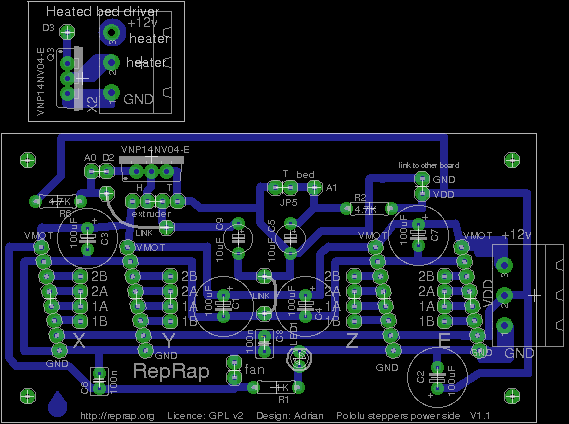
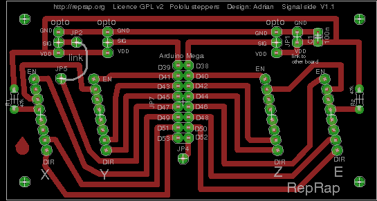
As Nophead has pointed out, that Pololu driver is a nice design, but with one big shortcoming: it will run hot, and is difficult to cool because it's so small. So what I've done is to design the electronics in such a way that they both perform their function and act as a physical duct for the flow from a fan to direct their own cooling. A happy side-effect of this is that the resulting PCBs are very simple, and can be made single-sided without any thin tracks. That is to say, when we get RepRap making electronics, they will not represent too high a first hurdle.
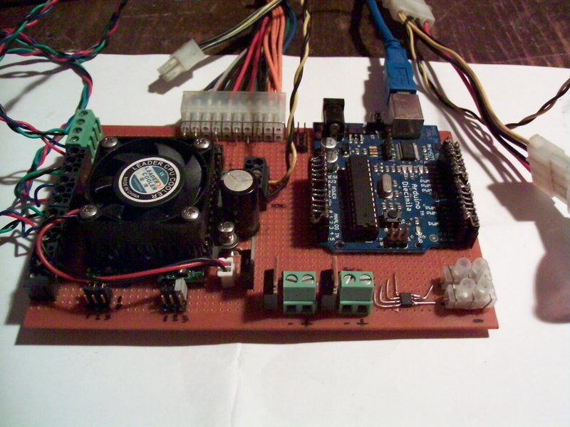
Indeed, so simple is the design that it is quite straightforward to make it on a couple of pieces of stripboard. That is how I prototyped it.
All the Eagle design files for this are in the repository here, along with mechanical alterations and additions to the Mendel design to accommodate them.
The latest copy of the standard RepRap firmware in the subversion repository supports this design. Set MOTHERBOARD to 3 in your configuration.h file and compile for the Arduino Mega.
Pololu do a DC motor controller with an identical geometry, so it should be possible to make a similar device with - say - two stepper drivers and two DC motor drivers that would control further extruders.
Schematic
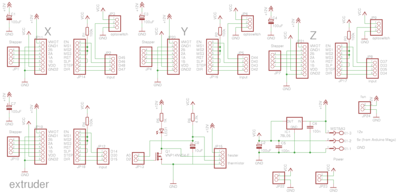
Here is the schematic. The Pololu boards have 16 connections that come out of the edges on a 2.54mm pitch. Those are the twin columns of 8-way connectors shown on the schematic. I deliberately did not create a single Eagle library device for the Pololu boards, as half their connections go to one PCB, and the other half to the other. The whole thing makes a box structure that both simplifies connections and also ducts the cooling air, as mentioned above.
The Arduino Mega connections are the ones labelled A0, D34 etc.
Leave the 78L05 5v regulator off if you connect Vdd to the 5v output of the Mega.
Making the electronics using stripboard
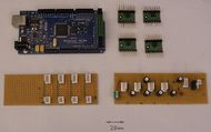
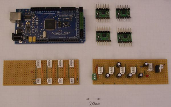
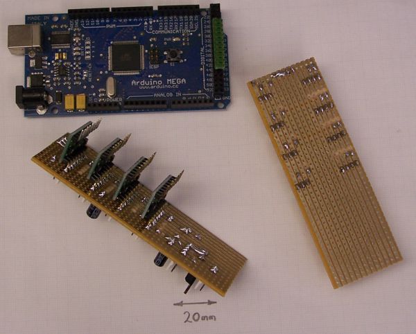
Here are all the components except the connecting wires. I built it on two pieces of stripboard 13 strips wide by 41 holes long. Start by soldering 90o pin headers into the Pololu boards so the connections stick out sideways.
Here are the reverse sides of the boards, showing the track breaks. It is really important to double check everything at this stage because, after you do the final assembly, it will be very difficult to make corrections.
Solder all the Pololu boards onto one piece of stripboard first. Make this the power side (with VMOT, VDD and two GNDs). Run a bead of solder along the tracks for VMOT and the two GNDs to give plenty of current carrying capacity.
Now for the tricky bit...
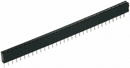
No. Not yet. I just had a better idea. Instead of soldering in the Pololu boards, put SIL socket strip in to accommodate them like this:
Then the whole device would just push-fit together. Best check the current capacity of the connections of the strip you choose. Or you could solder the power side and use the stripboard on the signal side; that way you'd still get a push-fit device, but with the solder to take the motor currents.
Back to doing it the tricky way...
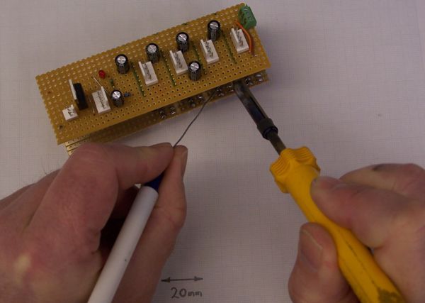
...you have to reach in with the soldering iron to do the second stripboard. You may find it easier to put the solder in from the other side to the one shown in this photograph.
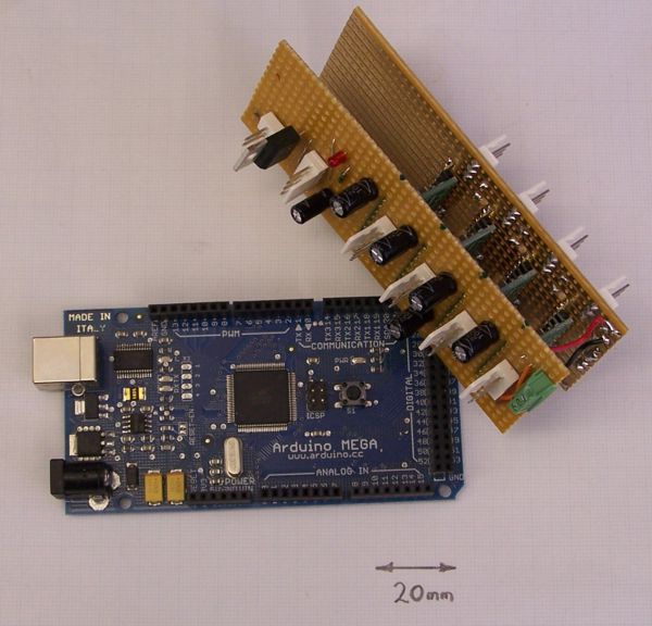
Here is the finished device. Note the red and black wires - they carry Vdd and ground from the power-side stripboard to the signal-side one.
It is intended to mount the whole thing on a fan in such a way as the entire fan flow is ducted between the four Pololu boards to cool them.
Simple PCBs
I've done a couple of draft PCB designs. They are in the repository. I'll probably change them a bit: it would be convenient if the connections to the Arduino Mega were in the form of one double-row pin header, as that would allow just one ribbon cable to be used for all the signals. It would also be neat to be able to cant the Pololu boards at a slight angle so that one could get a screwdriver in to adjust the current-setting potentiometers more easily.
Video
Finally, here's a brief video...
<videoflash type="vimeo">9962055|640|480</videoflash>
Other Pololu Designs
Triffid Hunter
Rapatan
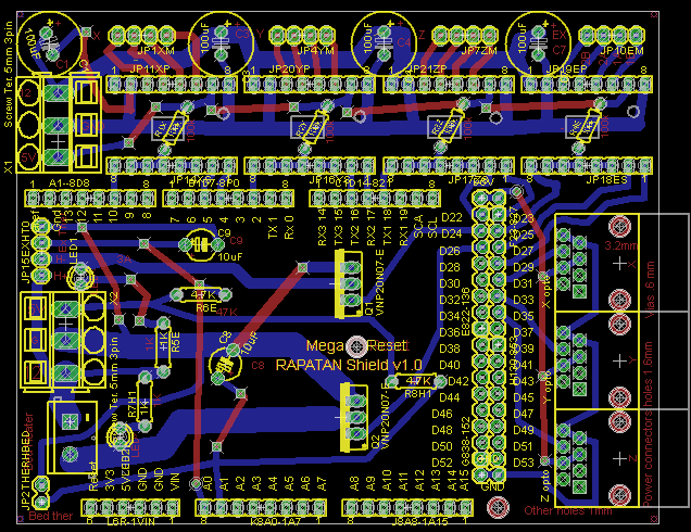
Complete electronics consisting of 2 stackable boards, RapatanShield_base_board_V1.0 on top of Arduino_Mega_Board. (see link for further details)
Base board provides ; 4 steppers control , 3 opto end stops, 2 heaters (Heater bed 10A, & Extruder Heater 3A) and 2 Thermistors for temperature control.
[1] Rapatan_Shield_base_board_V1.0
[2] Arduino Mega
Johnnyr
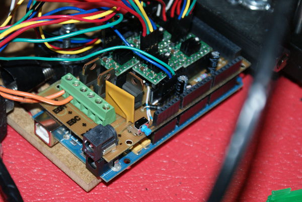
Another shield design for the Arduino Mega, plugging the Pololu stepper driver boards into the shield, is being documented at Arduino_Mega_Pololu_Shield . This variant is being designed so that the shield PCB itself can (hopefully) be created (masked) on a RepRap.
mike mackenzie
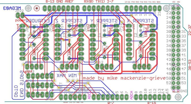
this is my addition for this project, this is a continuation of my first one, i has 4 pololu stepper drivers on it, 6 opto end stops connectors, and a power input for the stepper drivers i will post a picture has soon has i can figure it out but for now here is a link to my thingiverse [3]
ljyang
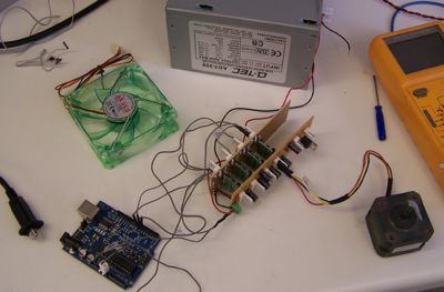
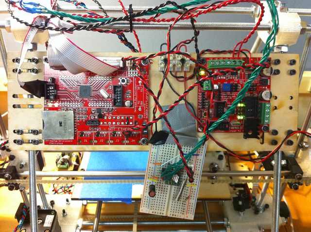
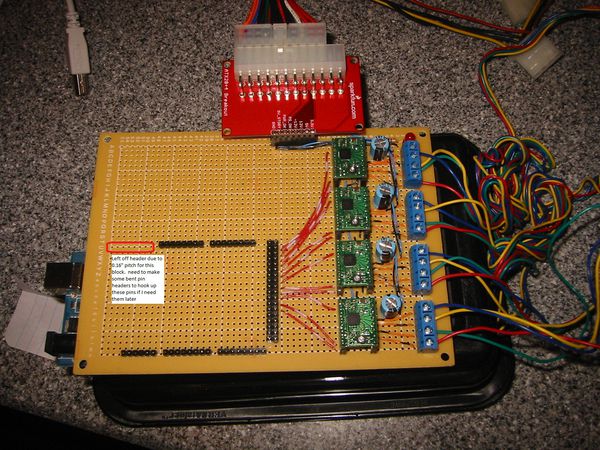
This is my setup right now for my repstrap. Should have the rest of the electronics ordered and setup shortly.
Dave M.
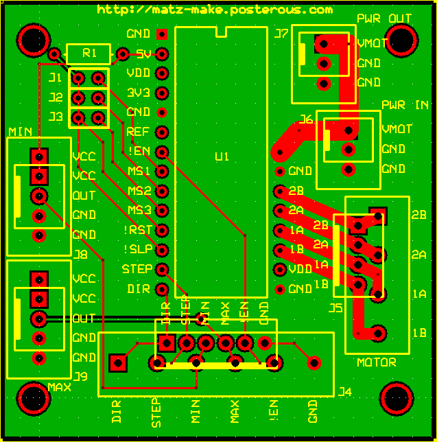
This is a board I'm planning on making to give MakerBot users an upgrade path to the Pololu driver that fits into the existing mounting holes. I have min/max endstop support, along with jumper-selectable step sizes. All connections can be configured with 0.1" connectors like the MTA100, or you can use terminal blocks to do your wiring. Comment on my blog if you have questions / comments / suggestions!
Tony Buser
I'm working on a Pololu Extruder Stripboard to interface with the current electronics but bypass the noisy inefficient extruder controller for driving the extruder stepper.
