PiBot Endstop
|
English • العربية • български • català • čeština • Deutsch • Ελληνικά • español • فارسی • français • hrvatski • magyar • italiano • română • 日本語 • 한국어 • lietuvių • Nederlands • norsk • polski • português • русский • Türkçe • українська • 中文(中国大陆) • 中文(台灣) • עברית • azərbaycanca • |
Release status: working
| Description | Part of Pibot Electronics optical limit
|
| License | |
| Author | |
| Contributors | |
| Based-on | [[]]
|
| Categories | |
| CAD Models | see files
|
| External Link |
Contents
Description
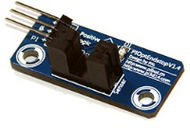
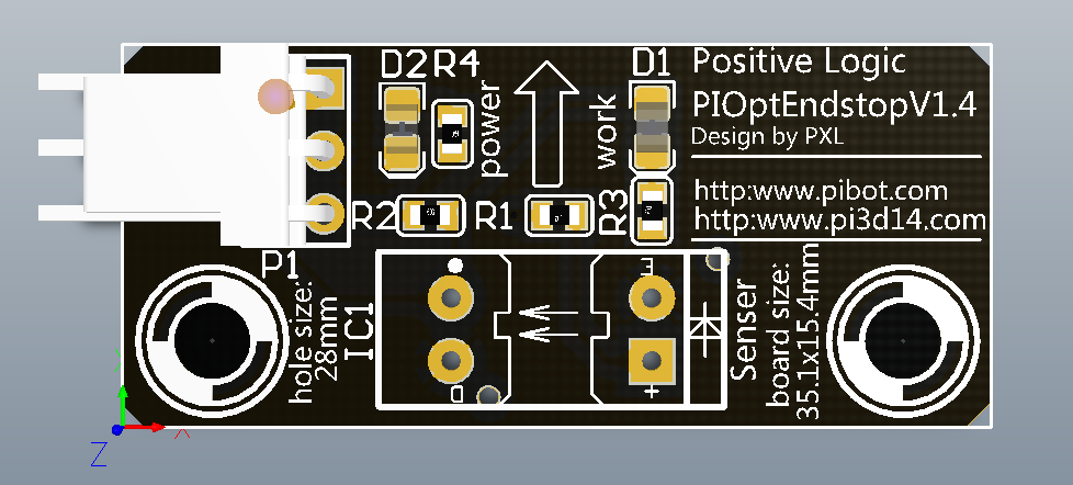
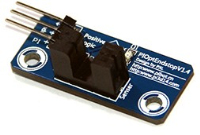
The Pibot_endstop is a 35x16mm PCB based on transmission type infrared sensor File:ITR9606-F.pdf | File:ITR9608-F.pdf, with two fix hole 28mm.
It is a non-contact transmission sensing devise, which with fast response time and high sensitive.
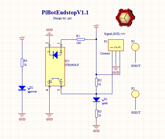
It is a positive logic electronic model,with 5v DC power pin, GND pin, and digital output pin.
It is powered by 5V DC, and has dual output (analog and digital).
If nothing stop the infrared illumination Photosensitive three Aurora, it output a low voltage; on the contrary, output high voltage.
I notice a very innovative design which based on Hall EffectHall-Θ, it very cool.
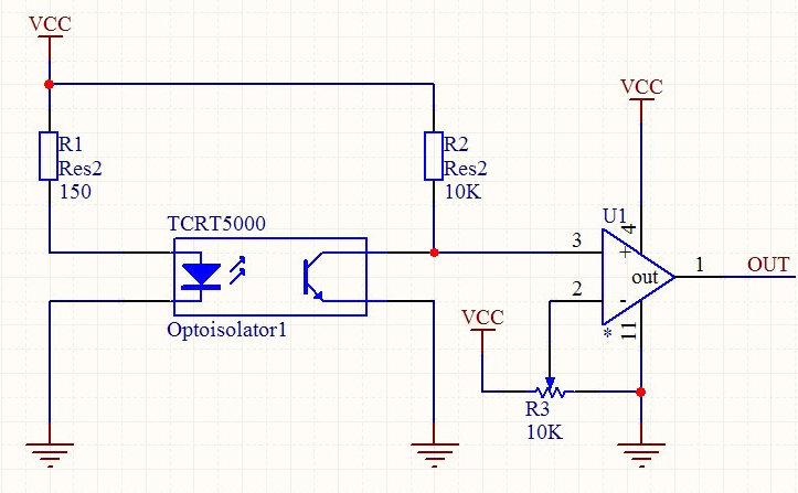
At same time, I found a solution that is use the reflective type infrared sensor and analog Comparator Amplifiers.
So,both the Analog and Digital signal can be output.I believe an amazing design would come from you.you can contact me [ PXL]
Price for complete pibot endstop $ 3,- (soldered, incl. 100mm cable and connector)
For purchasing or more information, please contact PiBot, or one of the resellers.
All parts are licensed under CC BY-NC-SA 3.0
Test & Work
hardware test
- Plug in the 5v-DC, if it is correctly connect,the power LED will lighten(red one).
- Then, use a slice plug in the 5mm trough ofITR9606-F|ITR9608-F, the work LED lighten(blue one).
If you finish above steps, congratulations, you have been finish the hardware test.
connection and software Debug
- Now, you can connect your cable, and plug in your mother board.
- If an Repetier firmware is used in your mother board, you can test the connection of these pins.
- Open Repetier-Host, click the "Manual Control", then, input "M119"in the "G-Cod edit box".
- Plug in the slice or not, you will get the status change of the endstop in the Host's "Show in log window".
Board images
Parts List
| Qnty | PartNr | Device | Footprint |
| 2 | D1,D2 | Blue,Red | led-0805-a |
| 1 | R1 | 180 | 0603ar |
| 3 | R2, R3, R4 | 1K | 0603ar |
| 1 | IC1 | IRF9606-F/IRF9608-F | transmission infrared sensor |
| 1 | Connector | 3P_Header-2.54 | SIP3/3P_HDR_OPT1 |
| 2 | P3,P2 | fix hole-3mm | fix hole |
| 100mm | Cable |
Development in future
Optical reflective type with a cool outline.
Chip solution: TCRT5000 ,LM358 or LM324(four channal) comparator, precision potentiometer
