PiBot Endstop
|
English • العربية • български • català • čeština • Deutsch • Ελληνικά • español • فارسی • français • hrvatski • magyar • italiano • română • 日本語 • 한국어 • lietuvių • Nederlands • norsk • polski • português • русский • Türkçe • українська • 中文(中国大陆) • 中文(台灣) • עברית • azərbaycanca • |
PiBot_Endstop
Release status: working
| Description | Part of PiBot Electronics optical limit
|
| License | |
| Author | |
| Contributors | |
| Based-on | [[]]
|
| Categories | |
| CAD Models | see files
|
| External Link |
- PiBot_Endstop
Contents
Description
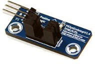
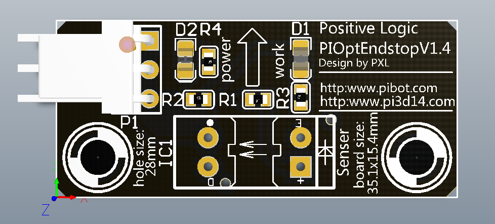
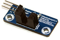
- The PiBot_endstop is a 35x16mm PCB based on transmission type infrared sensor File:ITR9606-F.pdf or File:ITR9608-F.pdf, with two mounting hole (M3 screw) distance; 28mm.
- It is a non-contact transmission sensing devise, which with fast response time and high sensitive.
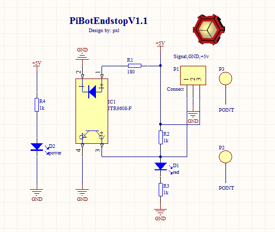
- It is a positive logic electronic model, with 5v DC power pin, GND pin, and digital output pin.
- It is powered by 5V DC, and has dual output (analog and digital).
- If nothing stop the infrared illumination Photosensitive three Aurora, it output a low voltage; on the contrary, output high voltage.
- I notice a very innovative design which based on Hall Effect Hall-Θ, it's very cool.
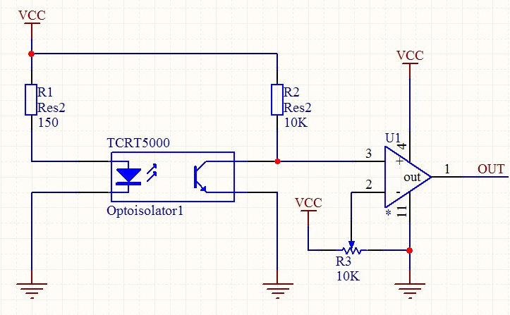
- At same time, I found a solution that is use the reflective type infrared sensor and analog Comparator Amplifiers.
- So that,both the Analog and Digital signal can be output.I believe an amazing design would come from you.you can contact me Pan Xinlong.
- Price for complete PiBot Endstop - (soldered inc. connection terminal).
- For purchasing or more information, please contact PiBot, or one of the resellers.
- All parts are licensed under CC BY-NC-SA 3.0.
Purchase URL
Test & Work
Hardware Test
- Plug in the 5v-DC, if it is correctly connect,the power LED will lighten(red one).
- Then, use a slice plug in the 5mm trough ofITR9606-F|ITR9608-F, the work LED lighten(blue one).
- If you finish steps above, congratulations! you have been finish the hardware test.
Connection and Software Debug
- Now, you can connect your cable, and plug in your mother board.
- If an Repetier firmware is used in your mother board, you can test the connection of these pins.
- Open Repetier-Host, click the "Manual Control", then, input "M119"in the "G-Cod edit box".
- Plug in the slice or not, you will get the status change of the endstop in the Host's "Show in log window".
Board images
Parts List
| Qnty | PartNr | Device | Footprint |
| 2 | D1,D2 | Blue,Red | led-0805-a |
| 1 | R1 | 180 | 0603ar |
| 3 | R2, R3, R4 | 1K | 0603ar |
| 1 | IC1 | IRF9606-F/IRF9608-F | transmission infrared sensor |
| 1 | Connector | 3P_Header-2.54 | SIP3/3P_HDR_OPT1 |
| 2 | P3,P2 | fix hole-3mm | fix hole |
| 100mm | Cable |
Development in future
Optical reflective type with a cool outline.
Chip solution: TCRT5000 ,LM358 or LM324(four channal) comparator, precision potentiometer
