HuxleyZAxis
General
This page and its peers should guide you through assembling a RepRap Huxley from the TechZone kit, or from parts you have printed which are the same as the TechZone parts. It is a work in progress, and needs some help, feel free to edit this document to add comments of you your own, or contact us [here] and send us messages asking us for better clarification or details.
I am starting by posting the pictures I have, and over the next few days, I will fill in the instructions and detials (24 Dec 2010)
Thanks,
Lambert (TechZone R&D/Support/Documenter)
You can access this page and it's peers (for the other parts of the Huxley assembly from the Main Huxley page or from the TechZone Huxley Page
Contents
The Z Axis should be put in after the frame and Y axis have been squared, and trued. Information about how to do that can be found here. You should have tightened all nuts and used threadlock on them if you are going to (I recommend that you use threadlock). If you perform the following steps before squaring and trueing up the frame and Y axis, it will be in the way and will make that process more difficult.
Drive Rods
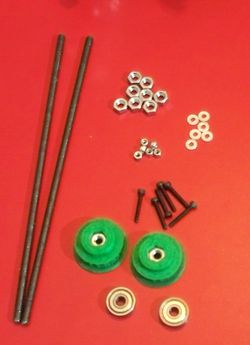
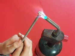
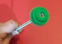
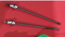
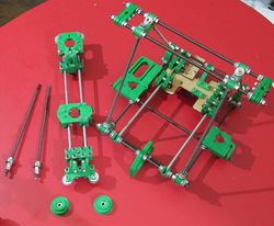
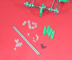
On the left is a picture of the parts used to assemble and prepare the drive rods for the Z axis. On the right is an assembled and prepared Z Drive rod- (2) 6mm threaded rod (the las 2 in the set) they are about 215mm or 8-1/2" long
- (2) Printed Drive Cogs (shown with nut already installed)
- (2) 626zz bearings
- (10) 6mm nuts
The following are shown in the picture but are not used until the next step (but I mised them in that picture...)
- (6) 3mm X 20mm bolts
- (6) 3mm Nylocs
- (12) 3mm washers --ok... the picture only shows 6...
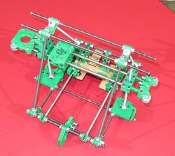
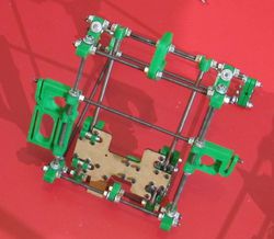
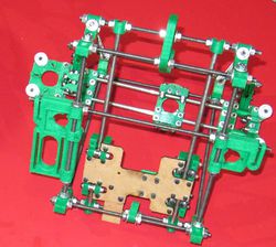
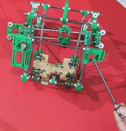
Install the X Axis onto the Z drive rods
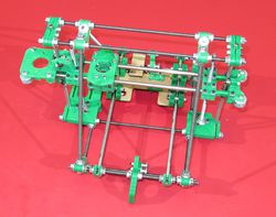
You will need the Huxley, the assembled X Axis, the two threaded drive rods from above and the printed drive cogs, along with the 3mm bolts, nuts and washers listed in the step above. NOTE although this picture has the Z smooth bar clamps in place, we do not yet put them on, that comes in the next step -- my pictures got ahead of my instructions, sorry.
Adding the Z Smooth bars
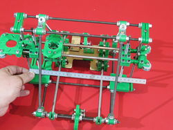
Aligning the Z Axis
